An SPB service connects multiple customer sites together across a provider-managed core network by creating a virtual zero-hop, Layer 2 switched domain.
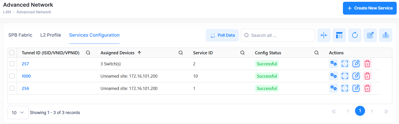
Use the Service Configuration screen to display information about all of the configured services. This screen also allows you to create, edit, or delete services. To access the Service Configuration screen, click on LAN > Advance Network under the “Configure” section of the OmniVista Cirrus Menu. and select the Service Configuration tab. The Service Configuration screen is displayed.
Creating a Service
To create a new service, click on Create New Service at the top of the Service Configuration screen. Create Service Profile screen appears.
There are six steps to configure a service.
-
Step 1 - SPB Service Settings: This will include basic and advance configuration fields.
-
Step 2 - Device Selection: Steps to plan on which device SPB must be configured.
-
Step 3 - SAP Configuration: Create SAP in selected access ports.
-
Step 4 - UNP Access Port Configuration: Enable UNP capacity for selected ports.
-
Step 5 - Configure UNP Mapping: Configure UNP which is mapped to the traffic.
-
Step 6 - Preview: Preview all the configurations done for the service
Each screen and its configuration steps are given below.
Step 1 - SPB Service Settings
Enter the Basic and Advanced SPB service configuration details to create a new service.
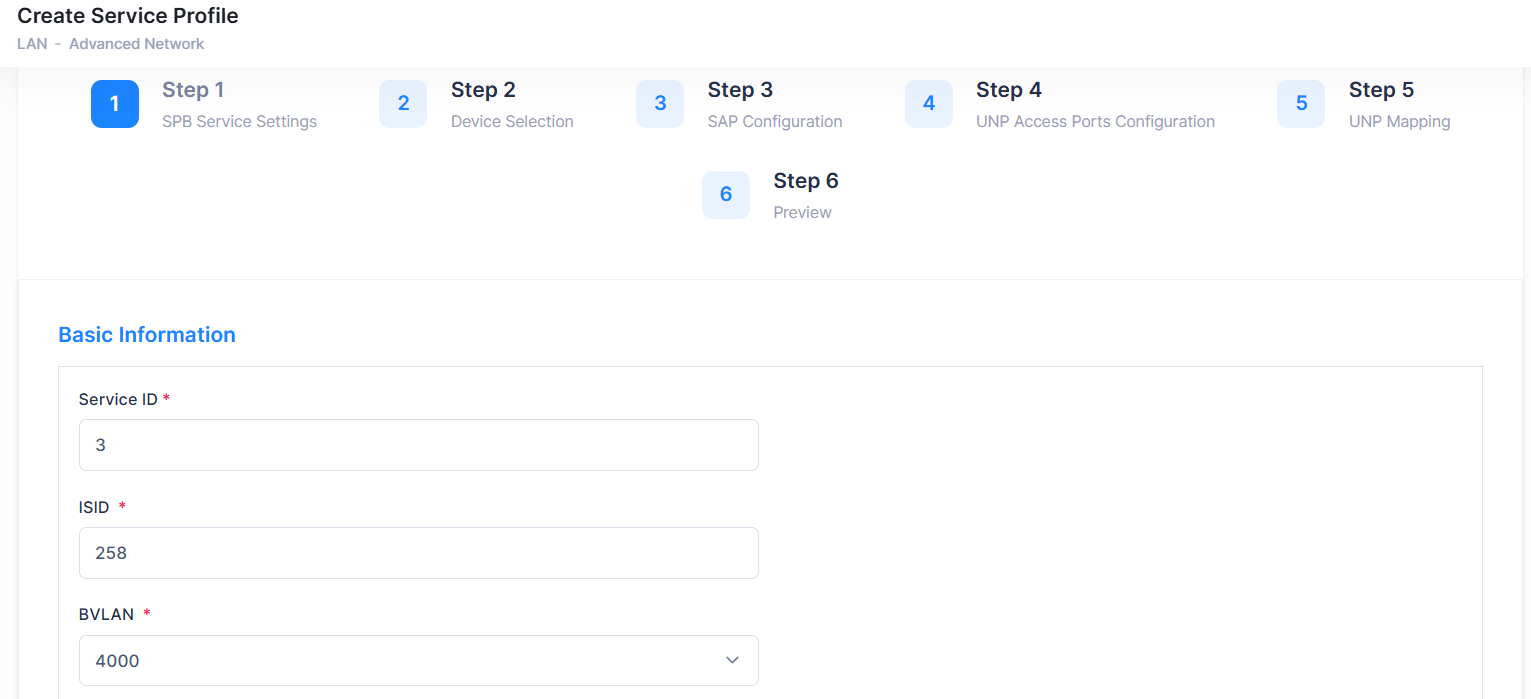
Basic Information
-
Service ID - Enter a unique numerical value to identify a specific SPB service. The valid service ID range is 1 - 32767. The field is pre-filled with a Service ID is auto-generated by OmniVista. based on the last highest Service ID configured (current highest value + 1). If you want to modify it, you must avoid entering an exiting ID.
-
ISID - Enter the service instance identifier (I-SID). An ISID is required on a switch configured as a Backbone Edge Bridge (BEB). It identifies a backbone service instance that will tunnel the encapsulated data traffic through the network between BEBs. The ISID is bound to a BVLAN ID and a Service Manager SPB service ID when the service is created. The valid range is 256 - 16777214. The field is pre-filled with a ISID is auto-generated by OmniVista based on the last highest ISID configured (current highest value + 1). If you want to modify it, you must avoid entering an exiting ID.
-
BVLAN - Select the BVLAN for the Service. The drop-down displays BVLANs configured on the switch. BVLANs are configured on a switch using the CLI. The field is pre-filled with a BVLAN value is polling from device. You can either retain the same value or modify it as required from the drop-down list.
-
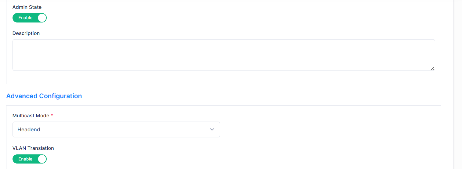
Admin State - Administratively enable or disable the service by selecting Enable or Disable option. You can either retain the same value or modify it as required.
-
Description - Enter a description for the service.
Advanced Information
-
Multicast Mode - The multicast replication mode for the service. Make sure that the same multicast mode is used across all nodes for a given SPB BVLAN. Tandem nodes and headend nodes cannot communicate with each other. You can either retain the same value or modify it as required.
-
Headend - When an SPB service is configured to use the headend mode, a non-unicast packet received on an SPB access port is replicated once for each receiver in the PBB network using its unicast base MAC (BMAC) address.
-
Tandem - When an SPB service is configured to use the tandem mode, a non-unicast packet received on an SPB access port is replicated once at each node using the multicast group address.
-
-
VLAN Translation - Enable or disable VLAN translation for the service by selecting the Enable or Disable option. By default, this field will show as Enable.
-
Enable - Select this option to configure the status of egress VLAN translation for all the service access points (SAPs) associated with the specified service.
-
Disable - select this option to allow the frames simply egress without any modification of the VLAN tags, that is, the frames are transparently bridged without tag modification.
-
-
Stats - Enable or disable statistics gathering for the service by selecting the Enable or Disable option. By default, this field will show as Enable.
-
Enable - Select this to enable ingress and egress statistics collection for packets flowing through the service access point (SAP) or service distribution point (SDP) bindings associated with the service.
-
Disable - Select this option to disable statistics collection for a service.
-
-
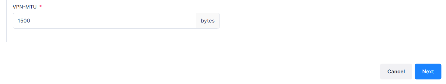
VPN-MTU - Enter the largest frame size the service can handle. The valid range is 1280 to 9100. By default, this field displays a value of 1500.
When you are finished, click on Next button or or click Step 2 to proceed to next step of service configuration, which is Device Selection or click on Cancel button to cancel the configuration. This will take you back to the Service Configuration main page.
At any point of time, click Previous button. This will take you to the previous configuration screen.
Step 2- Device Selection
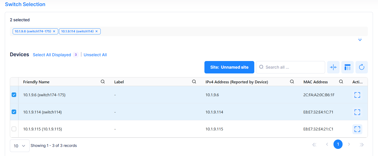
This screen allows you to to select the devices on which SPB is to be configured.
-
Select Site lists the available devices for the selected site. Device selection is filtered by both the selected site and the BVLAN chosen in Step 1. (These devices are referring to real physical equipment installed in one site.). To view the devices for all the sites, select “All Sites” from the drop-down.
-
Select the device/s on which SPB is to be configured by clicking on the checkbox next to the device name. Click on Select All Displayed to select all the devices. Click on Unselect All to unselect the devices. The selected devices will be listed on top as shown in the above screen.
-
Click on Next or Step 3 to proceed to next step of service configuration, which is SAP Configuration or click on Cancel button to cancel the configuration. This will take you back to the Service Configuration main page.
-
At any point of time, click Previous button. This will take you to the previous configuration screen.
To display additional information about a specific device, click on the Additional Information icon under the Actions column. Additional Information screen is displayed. The information displayed on this screen is defined below.
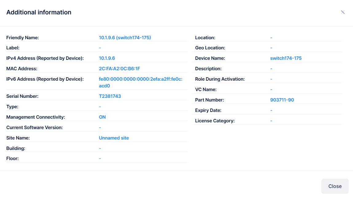
The following information is displayed for each device:
-
Friendly name - The name assigned to the device is derived from the Preferred Device Naming convention specified in the user preference settings. By default, the Friendly Name is set to IP Address (System Name).
-
Label - Label given for the device.
-
IPv4 Address - The IPv4 address of the device.
-
MAC Address - The MAC address of the device.
-
IPv6 Address - The IPv6 address of the device.
-
Type - The model number for the device.
-
Management Connectivity - The following management connectivity values indicate the various stages of device connectivity with OmniVista Cirrrus.
-
Blank - The device is in an initial state (not yet onboarded).
-
On - When a device is successfully provisioned or OmniVista Cirrus receives heartbeat from the device, management connectivity transitions to “On”.
-
Unknown - If OmniVista Cirrus does not receive any heartbeat, the management connectivity status transitions from “On” to “Unknown”.
-
Off - After a certain amount of time with no heartbeat, the management connectivity status transitions from “Unknown” to “Off”.
-
-
Current Software Version - The current software version on the system.
-
Site Name - The name of the site on which the device is declared.
-
Building - The name of the building in which the device is located.
-
Floor - The name of the floor on which the device is located.
-
Location - Where the device is physically located.
-
Geo-Location - GPS Coordinates of the localized device.
-
Device Name - The name of the device.
-
Description - The description given for the device.
-
Role During Activation - The role of the device during activation (Master, Slave).
-
VC Name - The serial number of the master switch in a VC configuration.
-
Part Number - The part number of the Access Point device or switch module/sub-module.
-
Expiry Date - The date and time the license expires.
-
License Category - The license that is assigned to the device based on the subscription model: CAPEX Subscription or Flexible Pay.
-
CAPEX Subscription Model - There are eight license categories that are assigned based on the device model. See Using the CAPEX Model online help for more information.
-
Flexible Pay Model - Essential (APs and Essential switches) and Advanced (Advanced switches and Core switches). See Using the Flexible Pay Model online help for more information.
-
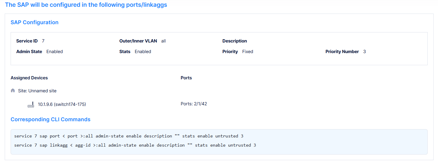
Step 3- SAP Configuration
A SAP identifies the location where customer traffic enters the PBBN edge, the type of customer traffic to service, parameters to apply to the traffic, and the service that will process the traffic for tunneling through the provider network.
Each SAP is comprised of an access port or link aggregate and an encapsulation type value. Access ports are customer-facing ports that reside on a provider edge router. Traffic received on these ports is classified for one or more SAPs and forwarded onto the intended destination by the associated SPB service.
Create Service Profile screen allows you to configure a SAP (Service Access Point ) by associating a SAP ID with a Shortest Path Bridging (SPB) service. Configuring a SAP requires several steps.
-
-
Select the device/s on which the SAP configuration is to be done.
-
-
-
Create a SAP by associating a SAP ID with the SPB service. A SAP ID is comprised of an access port and an encapsulation value, which is used to identify the type of customer traffic (untagged, single-tagged, or double-tagged) to map to the associated service.
-
-
Access Interface Configuration
-
Assign a Layer 2 profile to the specified SAP.
-
Configure customer-facing ports or link aggregates as service access ports.
-
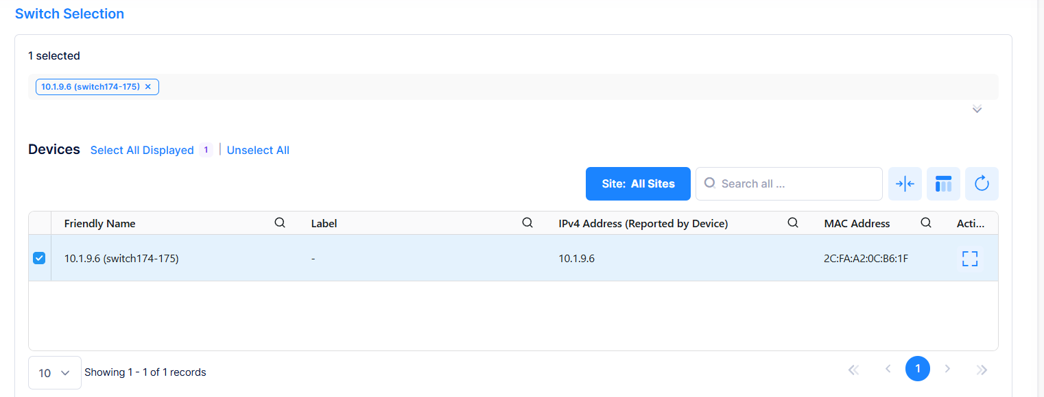
Switch Selection
-
The list of devices on which SPB is configured is displayed under “Switch Selection”.
-
Select the device/s on which SAP configuration is to be done by clicking on the checkbox next to the friendly name.
-
Click on Select All Displayed to select all the devices. Click on Unselect All to unselect the devices. The selected devices will be listed on top as shown in the above screen.
-
Click on Additional Information icon under the Actions column to view additional information about a specific device.
-
Global SAP Settings
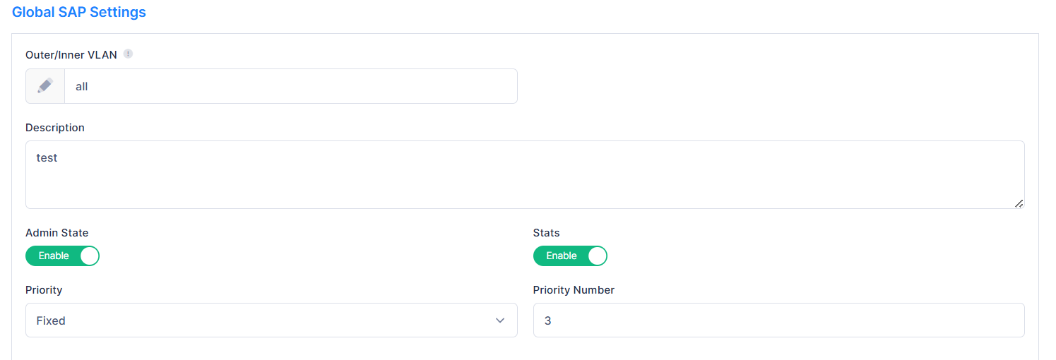
Enter the following SAP configuration details:
-
Outer/Inner VLAN - Enter the Outer and/or Inner VLAN. Entering an Outer or Inner VLAN is a way to map traffic tagged with the VLAN to the Service. The value must be these formats: 0-4094, [1-4094].[1-4094], all, [1-4094].all (for example, service 10 sap port 1/1/23:10, where 1/1/23 is switch port, 10 is inner VLAN).
-
Description - Enter a description for the SAP.
-
Admin State - Enable or disable the administrative status for the SAP.
-
Stats - Enable or disable the ingress and egress statistics collection for packets flowing through the SAP.
-
Priority - Select how packet priority is handled on the SAP by choosing Trusted or Fixed mode.
-
Trusted - Select this option to enable priority trust on the specified SAP. When Trusted is enabled, the SAP accepts and uses the 802.1p priority values carried in tagged incoming packets. Untagged packets use the default port priority value. By default, SAPs are configured as Trusted with a priority value of best effort (0) when the port is configured as an access port and associated with a SAP.
-
Fixed - Select this option to ignore any 802.1p priority values received in incoming packets and apply a fixed priority value to both tagged and untagged traffic on the SAP.
-
Priority Number - Enter the priority value to be applied when ‘Fixed’ mode is selected. This value is assigned to both tagged and untagged packets received on the SAP. Valid values range from 0 (lowest) to 7 (highest).
-
-
Access Interface Configuration
Enter the following access interface configuration details:
-
Automatic Access Interface Configuration - Enable or Disable automatic access interface configuration. If Enabled, OmniVista automatically creates an SPB interface.
-
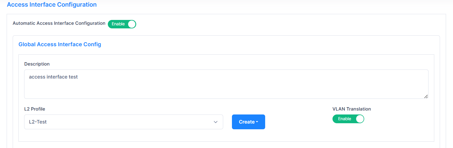
Global Access Interface Config - Enable or Disable Global Access Interface Configuration. If enabled, OmniVista creates a SAP based on the configuration below:
-
Description - Enter the description.
-
L2 Profile - Select an existing Layer 2 Profile from the drop-down menu or click on Create button) to create a new profile (Create L2 Profile). This assigns a Layer 2 profile to the specified service access port. Layer 2 profiles specify how control packets are processed on SAPs.
-
VLAN Translation - Enables or Disable VLAN Translation.
Enabling VLAN translation on an access port implicitly enables translation for all SAPs associated with that port. However, translation must also be enabled for the services associated with these SAPs. This ensures that all SAPs associated with a service will apply VLAN translation.
-
-
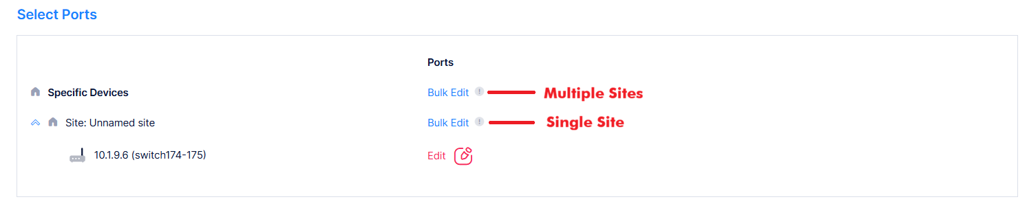
Select Ports - You can designate multiple SAP port/s for all selected devices across all the selected sites or a specific site in a single operation, or for the selected device/s under a specific site using the Edit option.
-
Bult Edit
-
Multiple Site - Click on this option to apply one or multiple SAP ports for all selected devices across all the selected sites in a single operation.
-
Single Site - Click on this to apply one or multiple SAP ports for all selected devices at this site in a single operation.
-
-
Select the required option and click Bulk Edit. Port Selection window is displayed.
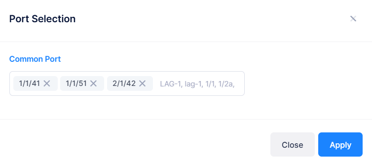
Common Port - Enter the ports to configure the same SAP port/s on all selected devices, and click on Apply button. Port Template must be in these formats: For example, LAG-1, lag-1, 1/1, 1/2a, 1/1-1/7, 1/1/1, 1/1/1a, 1/1/1-1/1/7.
-
Edit - Click on Edit option to apply one or multiple SAP ports for a specific device/s. The following window is displayed.
-
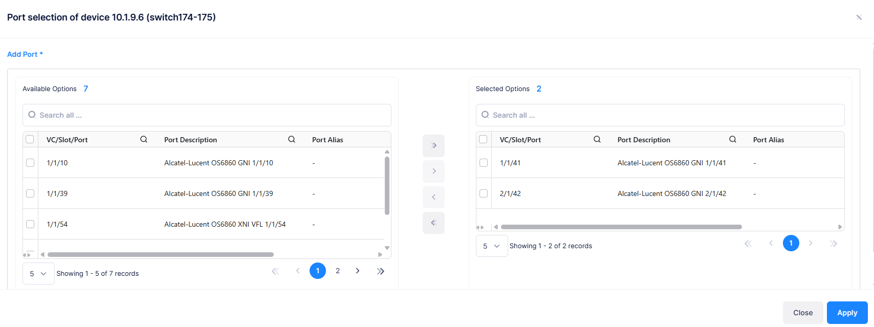
The Available Options tab lists SAP ports for selection. Select all or specific ports by checking the check box next to each port, then use the arrow keys to move them to the Selection Options tab. Click on the Apply button. Selected ports appear in the Select Ports tab.
-
When you are finished, click on Next button or Step 4 to proceed to next step of service configuration, which is UNP Access Ports Configuration or click Cancel button to cancel the configuration. This will take you back to the Service Configuration main page.
-
At any point of time, click Previous button. This will take you to the previous configuration screen.
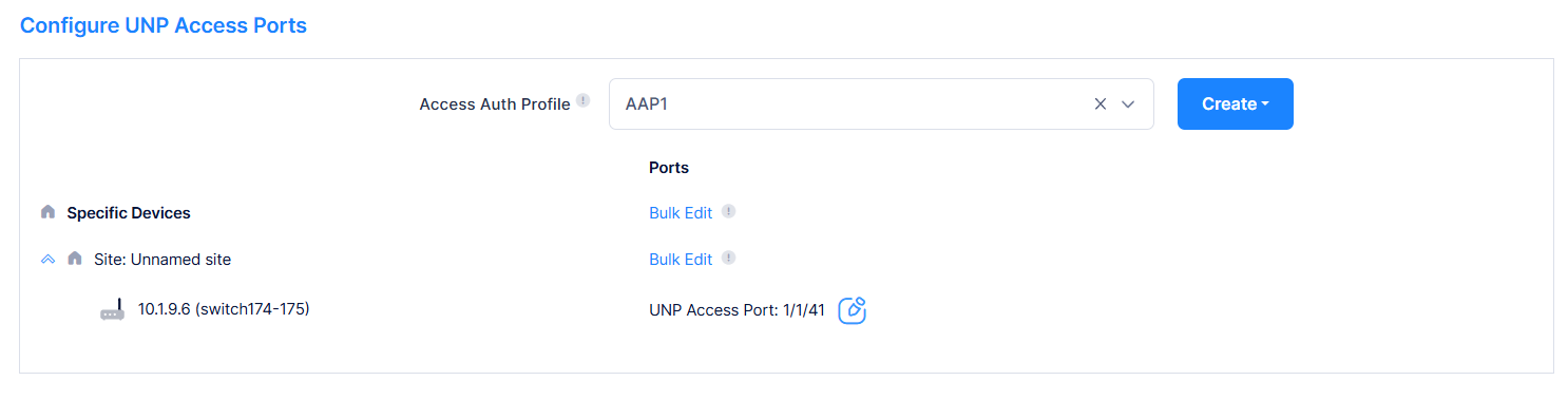
Step 4- UNP Access Port Configuration
Use this step to enable UNP functionality on the selected ports.
When a port is configured as a UNP access port, incoming traffic is classified based on service profiles. The classified traffic is mapped to a Service Access Point (SAP). Each SAP is associated with the UNP access port on which the traffic is received, an encapsulation VLAN value, and a service instance (currently an SPB I-SID). The encapsulation identifies the customer traffic that the SAP forwards on the associated service instance.
The Create Service Profile screen allows you to configure the UNP access port behavior.
-
-
Select the device/s on which the UNP access port configuration is to be done.
-
-
-
Select an Access Authentication Profile to be applied to traffic received on UNP Access Ports.
-
Switch Selection
-
The list of devices on which SPB is configured is displayed on the Switch Selection window.
-
Select the device/s on which UNP access port configuration is to be done by clicking on the checkbox next to the friendly name.
-
Click on Select All Displayed to select all the devices. Click on Unselect All to unselect the devices. The selected devices will be listed on top as shown in the above screen.
-
Click on Additional Information icon under the Actions column to view additional information about a specific device.
-
Configure UNP Access Ports
-
Access Auth Profile - Select an existing Access Authentication Profile to be applied to traffic received on UNP Access ports from the drop-down or click on the Create button to create new Access Authentication Profile (see the Access Authentication Profile online help).
-
Select Ports - Complete the fields below to designate a UNP access port/s.
-
Use Bulk Edit to apply one or multiple UNP access ports for all selected devices across all the selected sites, to apply for all the selected devices at this site in a single operation.
-
Use Edit to apply one or multiple UNP access ports for a specific device/s.
-
See Access Interface Configuration section for more information on steps to use Bulk Edit and Edit options.
-
-
Click on the Apply button. Selected UNP access ports appear in the Select Ports tab.
-
-
When you are finished, click on Next button or Step 5 to proceed to next step of service configuration, which is Configure UNP Mapping or click on Cancel button to cancel the configuration. This will take you back to the Service Configuration main page.
-
At any point of time, click Previous button. This will take you to the previous configuration screen.
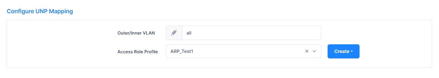
Step 5- Configure UNP Mapping
Configure the mapping of an existing service to the specified UNP profile. This type of profile mapping is only valid if the specified service is already configured; the switch does not dynamically create the service. The specified service ID is then used to dynamically create a SAP based on the specified tag value.
A static service ID cannot be removed until all the UNP users learned and forwarded on that service and associated SAPs are deleted.
Create Service Profile screen allows you to configure a UNP mapping.
-
Outer/Inner VLAN - Enter the Outer and/or Inner VLAN to be checked for tagged traffic. The value must be these formats: 0-4094, [1-4094]:[1-4094], all, [1-4094]:all (for example, 2:4094 or 2:all ...)
-
Access Role Profile - Select an existing Access Role Profile to be applied to the traffic from the drop-down or click on the Create button to create new Access Role Profile (see the Access Role Profile online help).
-
When you are finished, click on Next button or Step 6 to proceed to next step of service configuration, which is Configure UNP Mapping or click on Cancel button to cancel the configuration. This will take you back to the Service Configuration main page.
-
At any point of time, click Previous button. This will take you to the previous configuration screen.
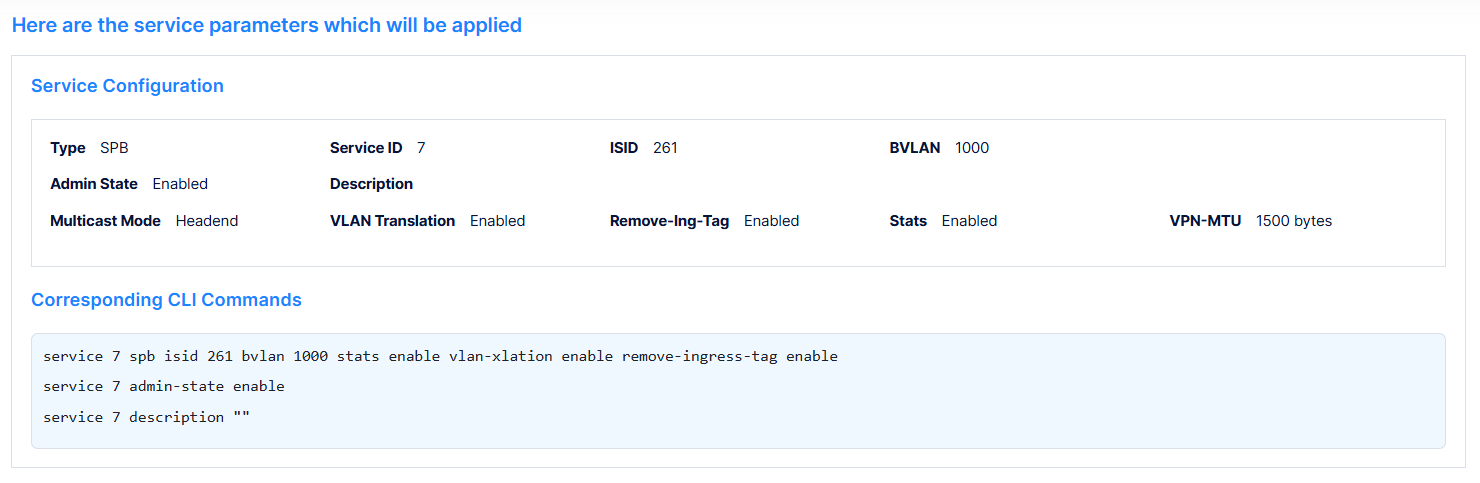
Step 6- Preview
This screen gives a preview of all the service parameters that will be applied on the device.
The following configuration details are displayed.
Service Configuration
|
Displays the service configuration parameters, and the corresponding service configuration CLI commands. |
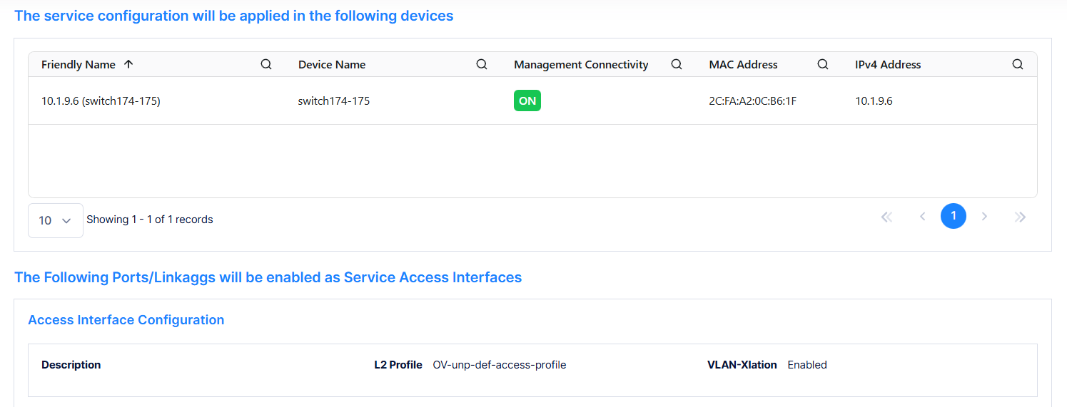
Switch Selection
|
Displays the list of devices to which the service configuration will be applied. |
|
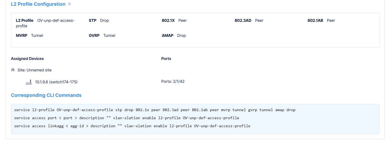
Access Interface Configuration and L2 Profile Configuration |
Displays the ports/linkaggs that will be enabled as Service Access Interfaces, the L2 profile configured for the port, and the corresponding CLI commands. |
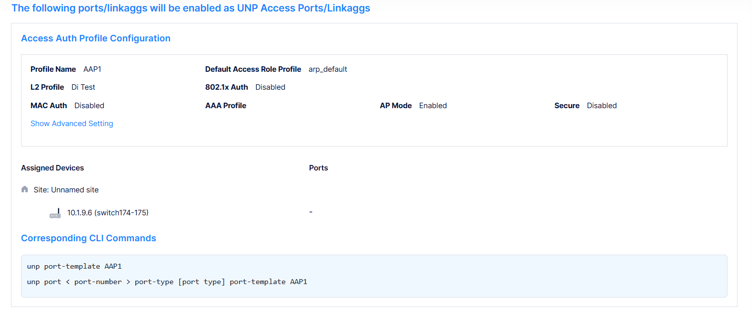
Access Auth Profile Configuration
|
Displays the Access Auth Profile configuration on the UNP access ports/linkagg, and corresponding CLI commands. |
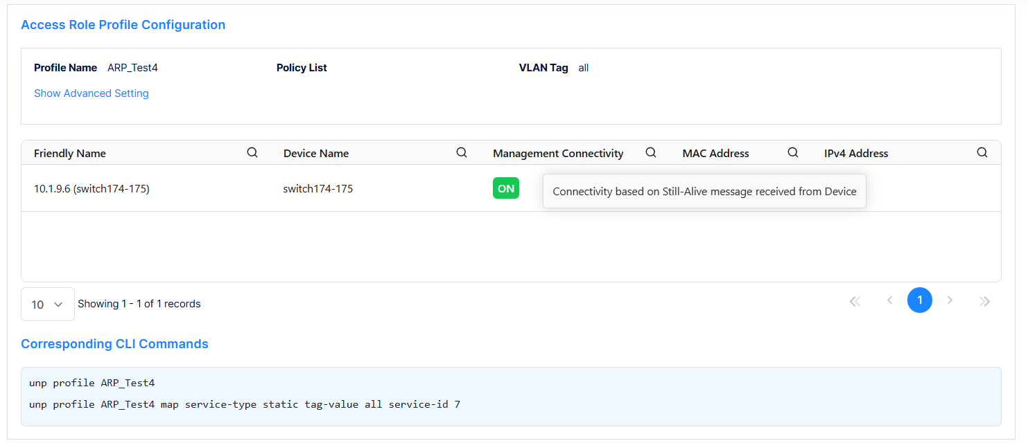
Access Role Profile Configuration
|
Displays the Access Role Profile configuration configured on the devices, and corresponding CLI commands. |
After previewing the configuration details, click on Create button to create a new service. or click on Cancel button to cancel the configuration. This will take you back to the Service Configuration main page.
Editing a Service
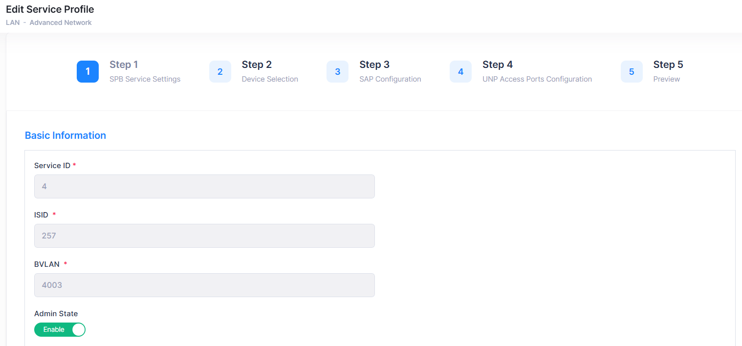
You can edit the parameter values for an existing Service by accessing the Edit Service Profile screen.
Use one of the following methods to access the Edit Service Profile screen.
-
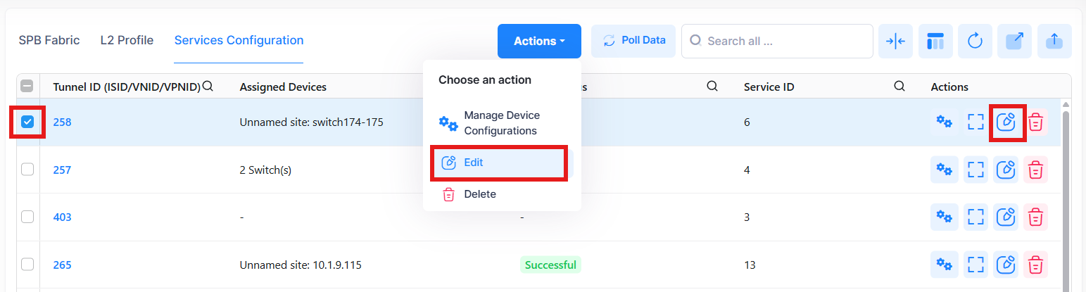
Select the service to edit by clicking on the check box next to the service ID, click on Actions, then select Edit from the drop-down menu.
-
Click on the pencil icon under the “Actions” column next to the profile that you want to edit.
The following Edit Access Auth Profile screen displays. Edit the fields as described above, then click on Save.
UNP Mapping modification is not allowed from the Edit Service Profile screen. (Step 5 - Configure UNP Mapping).
Deleting a Service
To delete a service, use one of the following methods to select the service you want to delete:
-
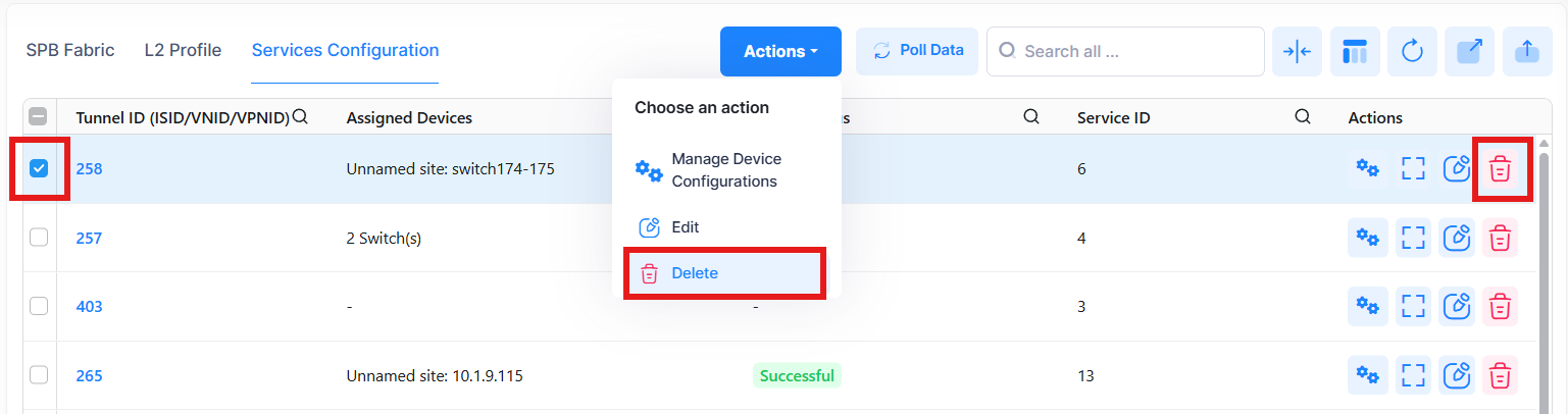
Select the service to delete by clicking on the check box next to the service ID, click on Actions, then select Delete from the drop-down menu.
-
Click on the trash can icon under the “Actions” column next to the profile that you want to delete.
When you select the service you want to delete, the following confirmation prompt appears:
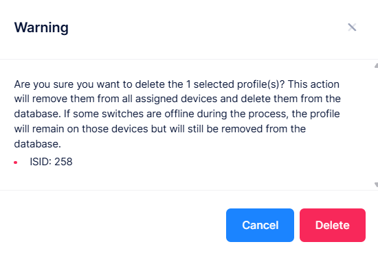
Click on Delete to confirm that you want to delete the service profile.
When a service is deleted, it will be removed from the Services Configuration. However, the UNP Access Ports Configuration (Step 4 - UNP Access Port Configuration) and/or the UNP Mapping (Step 5 - Configure UNP Mapping) still remain in Access Auth Profile and/or Access Role Profile.
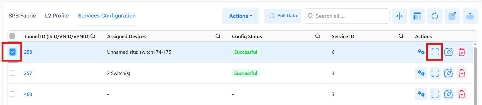
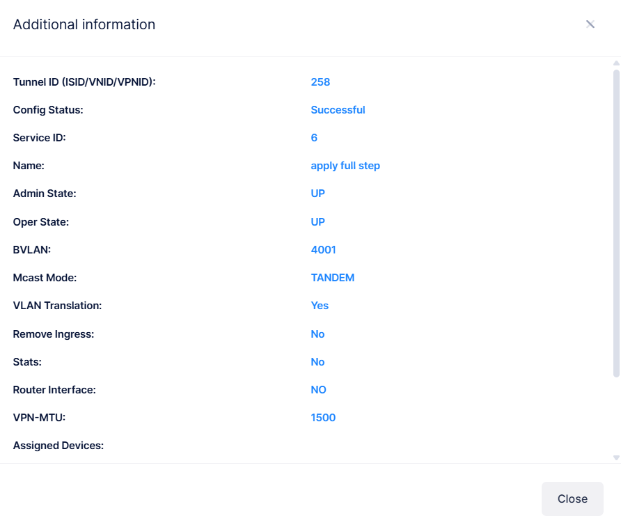
Display Service Additional Information
To display additional information about a specific service, click on the Additional Information icon under the “Actions” column. Additional Information screen is displayed.
-
Tunnel ID (ISID/VNID/VPNID) - The Tunnel ID used by the service.
-
Config Status - The status of applying the profile to devices (Successful, Failed, Pending, or Partially Failed).
-
Pending - The configuration is being pushed to the devices and has still not received any response from any device.
-
Failed - The configuration failed to apply to all the selected devices. Possible reasons include a timeout while applying the configuration due to the device being unreachable or a network issue, or the configuration being invalid and rejected by the device. Check alerts to identify the specific reason.
-
Successful - The configuration is pushed to all the selected devices successfully.
-
Partially Failed - The configuration is pushed to some devices successfully, while to others it failed or remains in a pending state.
-
-
Service ID - A unique numerical value to identify a specific service. It can also be auto-generated by a dynamically created service.
-
Name - The description for the service.
-
Admin State - The administrative state of the service (Up or Down).
-
Oper State - The operational state of the service (Up or Down).
-
BVLAN - The BVLAN associated with the service.
-
Mcast Mode - The multicast replication mode for the service (Headend, Tandem).
-
VLAN Translation -Indicates if VLAN translation is enabled for the service (Yes or No).
-
Remove Ingress - Indicates the " Remove Ingress Tag" status for the service. Currently, only default value is supported (No).
-
Stats - Indicates if statistics collection is enabled for the device (Yes or No).
-
Router Interface - The SBP interface. This interface is based on the IP interface linked to the service ID. Therefore, this field displays 'NO' unless configured manually on the switch through the CLI.
-
VPN MTU - The VPN MTU set for the service.
-
Assigned Devices - Lists the devices on which the service is configured, the device site information, ad the device configuration status.
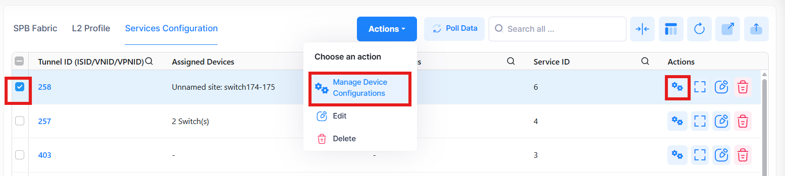
Display and Manage Service Configuration
The Service Configuration screen displays information for all services. To view detailed configuration for a specific service, use one of the following methods:
-
Select the service by clicking on the check box next to the service ID, click on Actions, then select Manage Device Configurations from the drop-down menu.
-
Click on the Manage Device Configurations under the “Actions” column next to the service.
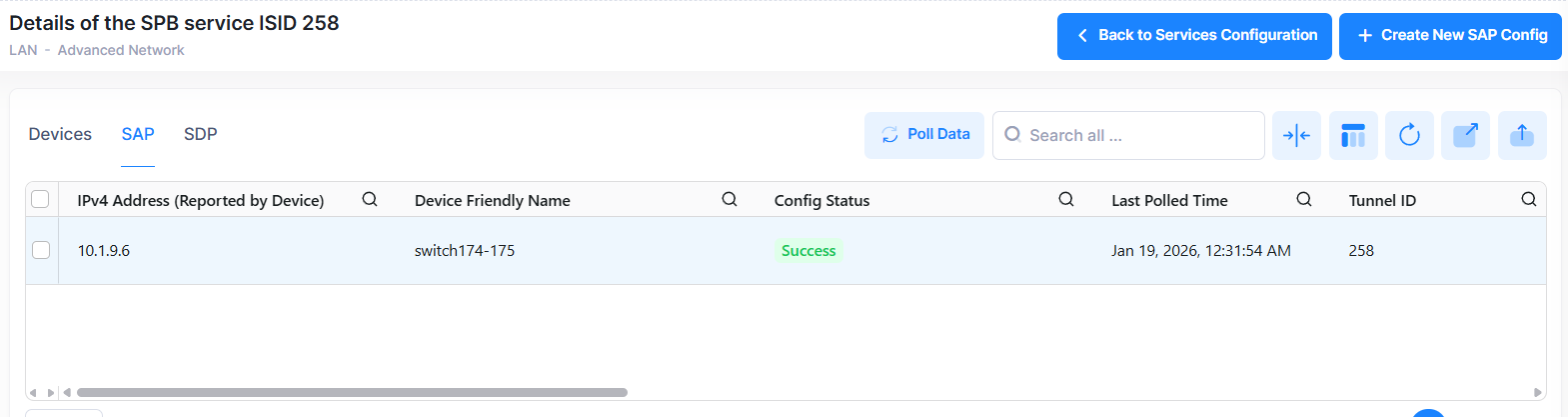
When you select the service you want to view, the following screen appears:
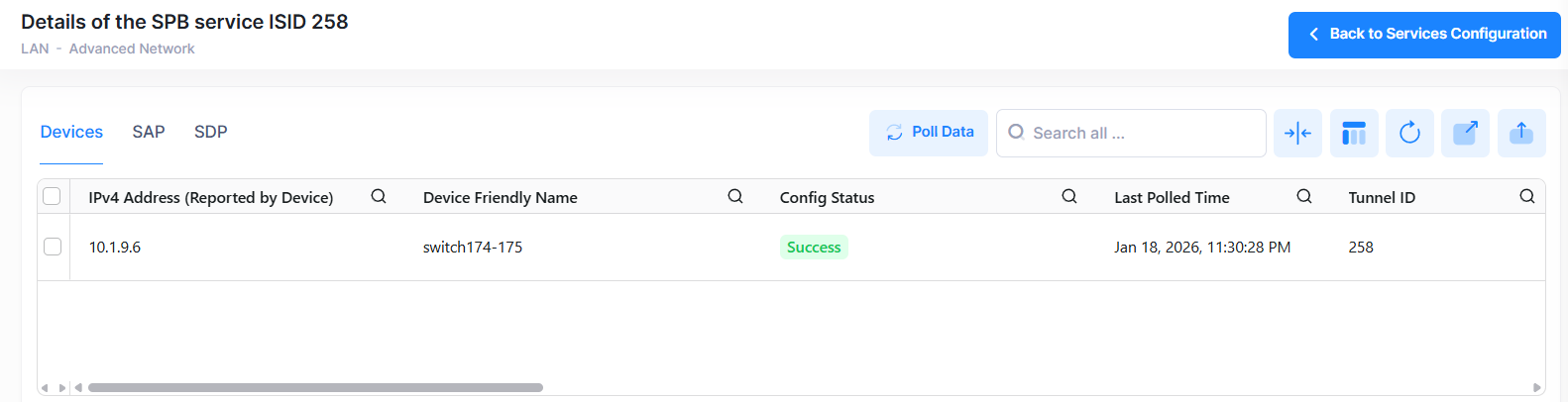
The screen has three tabs: Devices, SAP, and SDP.
-
Devices tab - Displays detailed information about devices on which the service is configured.
-
SAP tab - Displays detailed information for SAPs configured for the Service.
-
SDP tab - Displays detailed information for Service Distribution Points (SDP) configured for the service. An SDP is a logical service entity that tunnels traffic from one switch to another switch in the network. Manual configuration of SDPs and SDP bindings is not required for SPB services. SDPs are automatically created and bound to ISIS-SPB services as needed throughout the PBB network.
Device Information
The following information is displayed under Devices tab. This screen also allows you to view additional service information, edit, and delete a service. Click on the Back to Services Configuration button to go back to the main Service Configuration screen.
-
IPv4 Address - The IPv4 address of the device.
-
Device Friendly Name - The name assigned to the device is derived from the Preferred Device Naming convention specified in the user preference settings. By default, the Friendly Name is set to IP Address (System Name).
-
Config Status - The configuration status of the device. (Success or Failed or Pending).
-
Pending - The configuration is being pushed to the device and is still not receiving a response from the device.
-
Failed - The configuration failed to apply to the device. Possible reasons include a timeout while applying the configuration due to the device being unreachable or a network issue, or the configuration being invalid and rejected by the device. Check alerts to identify the specific reason.
-
Success - The configuration is pushed to the device successfully.
-
-
Last Polled Time - The last time the system synchronized data from the switch device.
-
Tunnel ID (ISID/VNID/VPNID) - The Tunnel ID used by the service.
-
Service ID - A unique numerical value to identify a specific service. It can also be auto-generated by a dynamically created service.
-
Name - The description for the service.
-
Admin State - The administrative state of the service (Up or Down).
-
Oper State - The operational state of the service (Up or Down).
-
BVLAN - The BVLAN associated with the service.
-
Mcast Mode - The multicast replication mode for the service (Headend, Tandem).
-
VLAN Translation -Indicates if VLAN translation is enabled for the service (Yes or No).
-
Remove Ingress - Indicates the " Remove Ingress Tag" status for the service. Currently, only default value is supported (No).
-
Stats - Indicates if statistics collection is enabled for the device (Yes or No).
-
Router Interface - The SBP interface. This interface is based on the IP interface linked to the service ID. Therefore, this field displays 'NO' unless configured manually on the switch through the CLI.
-
VPN MTU - The VPN MTU set for the service.
-
Nb SAPs - The number of SAPs configured on the device.
-
Nb SDPs - The number of SDPs configured on the device.
SAP Information
The following information is displayed under SAP tab. This screen also allows you to view additional service information, edit, and delete a service. Click on the Create New SAP Config button to configure SAP configuration for the service (see Global SAP Settings under Create New Service section). Click on the Back to Services Configuration button to go back to the main Service Configuration screen.
-
IPv4 Address - The IPv4 address of the device.
-
Device Friendly Name - The name assigned to the device is derived from the Preferred Device Naming convention specified in the user preference settings. By default, the Friendly Name is set to IP Address (System Name).
-
Config Status - The configuration status of the device. (Success or Failed or Pending).
-
Pending - The configuration is being pushed to the device and is still not receiving a response from the device.
-
Failed - The configuration failed to apply to the device. Possible reasons include a timeout while applying the configuration due to the device being unreachable or a network issue, or the configuration being invalid and rejected by the device. Check alerts to identify the specific reason.
-
Success - The configuration is pushed to the device successfully.
-
-
Last Polled Time - The last time the system synchronized data from the switch device.
-
Tunnel ID (ISID/VNID/VPNID) - The Tunnel ID used by the service.
-
Interface - The interface on which the SAP is configured.
-
Outer/Inner VLAN - The Inner/Outer VLAN configured for the SAP.
-
Service ID - A unique numerical value to identify a specific service.
-
Description - The description for the service.
-
Admin State - The administrative state of the service (Up or Down).
-
Oper State - The operational state of the service (Up or Down).
-
SAP Type - The SAP Priority setting (Trusted/Fixed).
-
Priority - The Priority Value if the SAP Priority Type is "Fixed".
-
Stats - Indicates if ingress and egress statistics collection for packets flowing through the SAP is enabled (Yes or No).
-
L2 Profile - Layer 2 profile assigned to the SAP.
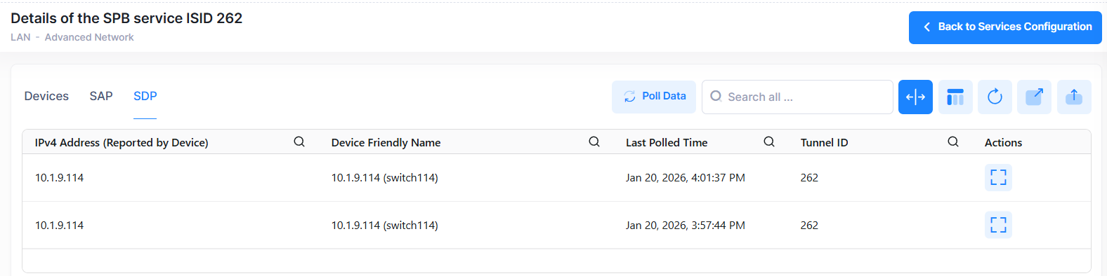
SDP Information
The following information is displayed under SDP tab. Click on the Back to Services Configuration button to go back to the main Service Configuration screen.
-
IPv4 Address - The IPv4 address of the device.
-
Device Friendly Name - The name assigned to the device is derived from the Preferred Device Naming convention specified in the user preference settings. By default, the Friendly Name is set to IP Address (System Name).
-
Config Status - The configuration status of the device. (Success or Failed or Pending).
-
Pending - The configuration is being pushed to the device and is still not receiving a response from the device.
-
Failed - The configuration failed to apply to the device. Possible reasons include a timeout while applying the configuration due to the device being unreachable or a network issue, or the configuration being invalid and rejected by the device. Check alerts to identify the specific reason.
-
Success - The configuration is pushed to the device successfully.
-
-
Last Polled Time - The last time the system synchronized data from the switch device.
-
Tunnel ID (ISID/VNID/VPNID) - The Tunnel ID used by the service.
-
Service ID - A unique numerical value to identify a specific service.
-
Interface - The SPB interface (network port) on which ISIS-SPB discovered the neighbor BMAC and BVLAN.
-
SDP Type - The SDP type (Dynamic).
-
SDP ID - The unique SDP identification number that is dynamically generated by ISIS-SPB.
-
Description - The description for the SDP.
-
Admin State - The administrative state of the SDP (Up or Down).
-
Oper State - The operational state of the SDP (Up or Down).
-
SDP Name - The SDP name.
-
SDP Info - The System ID (bridge MAC address) and associated BVLAN of the far-end SPB node of the tunnel defined by this SDP.
-
Stats - Indicates if statistics collection for the SDP is enabled (Yes or No).
-
TTL - The time-to-live (TTL) value for this SDP.
Polling Switches for Service Information
By default, OmniVista is automatically scheduled to poll switches for service information every one hour. To perform an immediate poll, click the Poll Data button on the Services Configuration screen. OmniVista will retrieve the latest data from the switches. To poll service data from all the switches, click Poll Data button in the SPB Topology page. This page will be updated with the most recent information.