Configure and Manage Layer 3 VLANs
The VLAN Manager IP Interface Screen is used to view configured IP interfaces on a device; and to create, edit, and delete IP interfaces on devices.
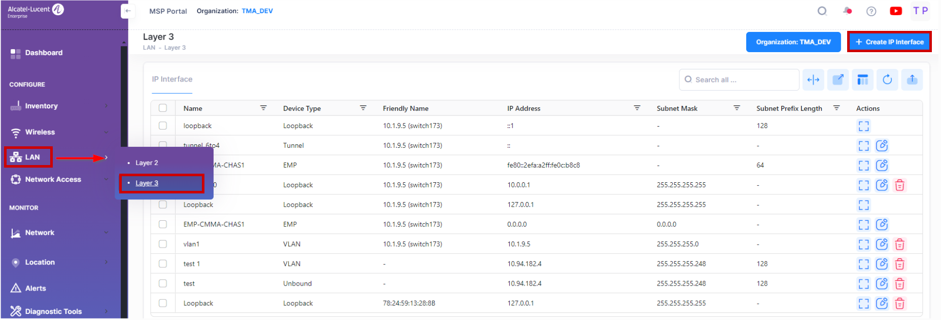
To manage the VLAN configuration, navigate to the IP Interface screen by clicking on LAN > Layer 3 under the “Configure” section of the OmniVista Cirrus Menu. The IP Interface screen displays.
Creating an IP Interface
The Create IP Interface screen is used to create an IP Interface on a device. To access this screen, click on Create IP Interface button.
The Create IP Interface screen provides the following step-by-step process for creating an IP interface:
Basic information - Configures the interface name, IP address, subnet mask and device type.
Switch Selection - Select the Switch or LAN devices from the available list to create an IP Interface .
Complete the following sections of the Create IP Interface screen, then click on Create Button.
Basic Information
Complete the fields as described below for configuring basic information to create an IP Interface.
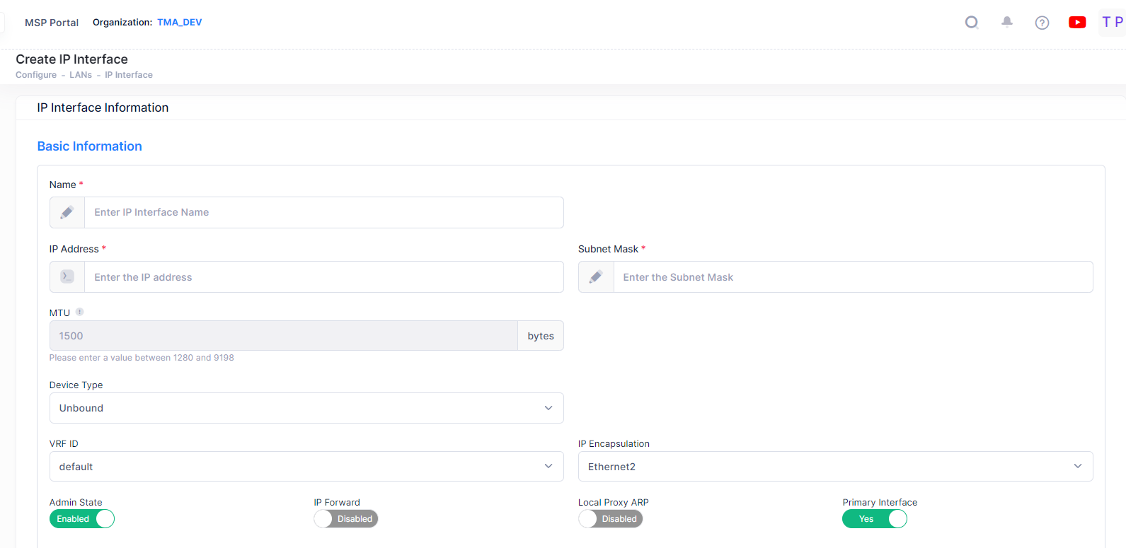
Name - The user-configured interface name.
IP Address - The IP address of the IP interface.
Subnet Mask - The IP interface subnet mask value. The default value for this field is based on which network class range the IP address falls within; Class A, B, or C. (255.0.0.0, 255.255.0.0, or 255.255.255.0).
MTU - The Maximum Transmission Unit size set for the interface.
Device Type - The type of device bound to the interface:
Unbound - No device is bound to the interface.
VLAN - Associates a VLAN with the interface. You must enter the VLAN ID in the VLAN ID field.
EMP - The Ethernet Management Port is bound to the interface.
Loopback - A loopback interface configured for testing.
GRE Tunnel - A GRE Tunnel is configured for the interface. You must enter the Tunnel Source and Destination.
IPIP Tunnel - An IPIP Tunnel is configured for the interface. You must enter the Tunnel Source and Destination.
VPN Tunnel -A VPN tunnel is configured for the interface. Please note that the device type "VPN Tunnel" option is only available if the VPN tunnel is created prior to the creation of the IP interface.
VRF ID - The VRF ID. If the device supports the Multiple VRF feature, select a VRF from the drop-down menu to assign the interface to a configured VRF instance (by default all interfaces are assigned to the Default VRF). You can assign a new interface to a VRF; however, you cannot edit the VRF ID of an existing interface. If the feature is not available on the device, the column will display "Default", indicating that the switch is operating as a single routing instance. VRF instances are created on the switch through the CLI or WebView application.
IP Encapsulation - The IP interface frame encapsulation value (Ethernet 2 or SNAP). The frame encapsulation determines the framing type the interface uses when generating frames that are forwarded out VLAN ports. Select an encapsulation that matches the encapsulation of the majority of IP VLAN traffic. (Default = Ethernet 2)
Admin State - The administrative state of the interface (Enable/Disabled). (Default = Enabled)
IP Forward - The interface forwarding status (Enabled/Disabled). A forwarding interface sends IP frames to other subnets. A "no forwarding" interface acts as a host only. It receives IP frames from other interfaces. (Default = Enabled).
Local Proxy ARP - Local Proxy ARP status (Enabled/Disabled). The Local Proxy ARP feature is an extension of the Proxy ARP feature, but is enabled on an IP interface and applies to the VLAN bound to that interface. When Local Proxy ARP is enabled, all ARP requests received on VLAN member ports are answered with the MAC address of the IP interface that has Local Proxy ARP enabled. In essence, all VLAN traffic is now routed within the VLAN instead of bridged. (Default = Disabled)
Primary Interface - If set to "Yes", designates the IP interface as the primary interface for the VLAN. If set to "No", the first interface bound to the VLAN becomes the primary by default. (Default = “Yes”)
Switch Selection
Select the devices from the available list on which you want to configure the interface. You can select the multiple devices also.
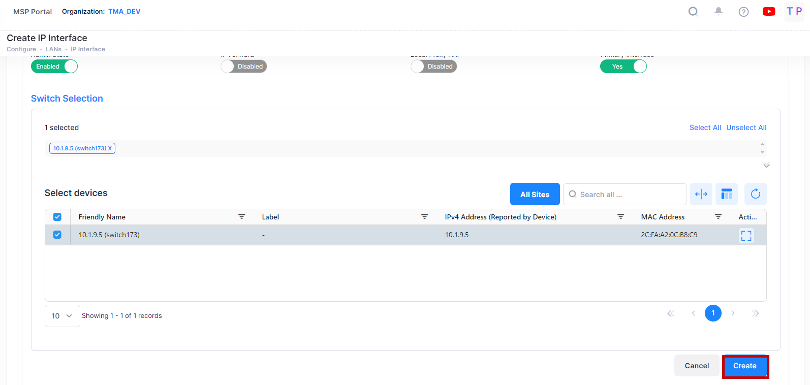
When you are done with the Switch Selection, click on Create button to complete the process of Creating an IP Interface.
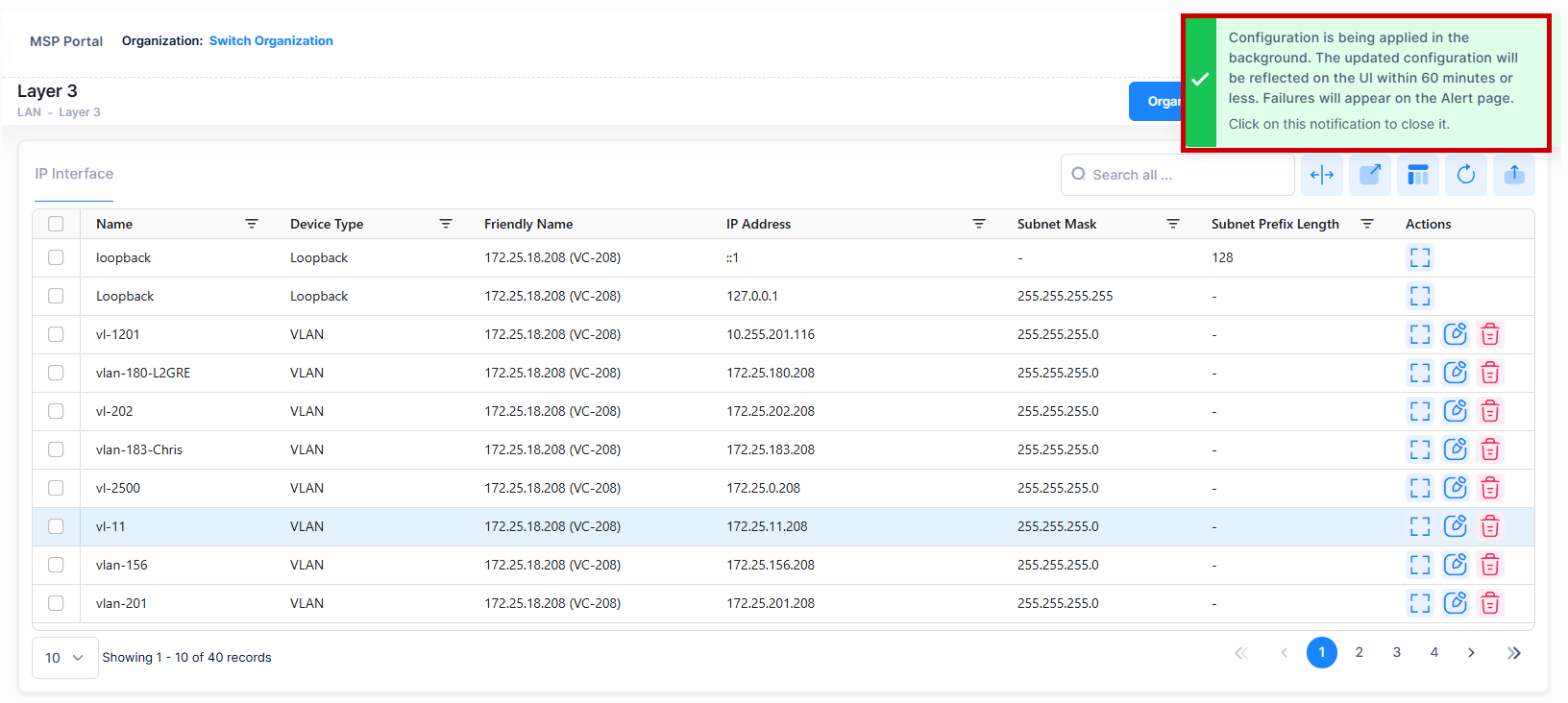
Note: When you requests for create/update/delete of an IP Interface from OminVista Cirrus R10, the configuration operation is done in the background. You can view the updated configuration results after certain time interval and the following alert message appears on the screen as shown below.
Editing an IP Interface
Select an IP Interface from the IP Interface List and click on the Edit icon under the “Actions” column. The Edit IP Interface Information screen opens on which you can edit the basic information and add new devices or remove existing devices from the configured devices list for an IP Interface, as described above.
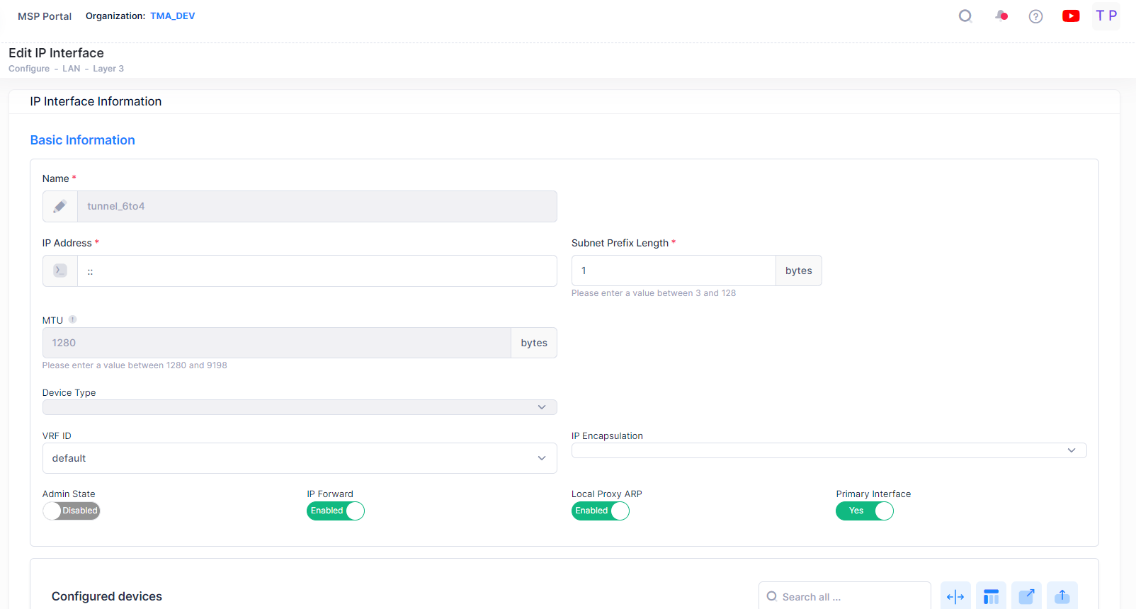
Click on Save button to save the changes.
Note: You cannot edit the Interface Name, Device type, and VRF fields. IP Interfaces with device type 'Loopback' and name as 'Loopback' (case sensitive for IPv4 interface and case insensitive for IPv6 interface) cannot be edited.
Deleting an IP Interface
To delete an IP Interface, use one of the following methods to select the interface you want to delete:
Select the IP Interface name to delete by clicking on the checkbox next to the list, click on Actions, then select Delete from the drop-down menu.
Click on the trash can icon under the “Actions” column next to the list that you want to delete.
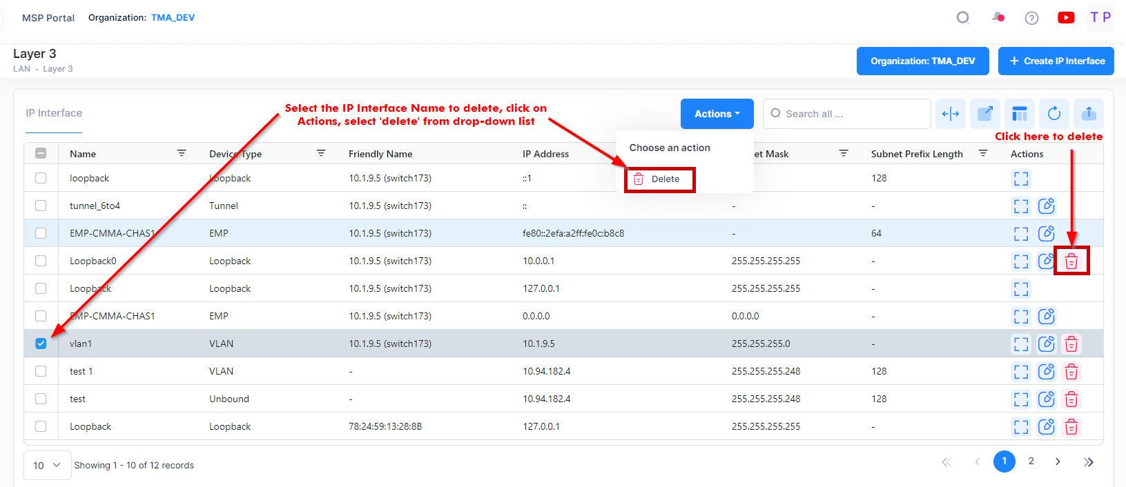
When you select the IP Interface you want to delete, the following confirmation prompt appears:
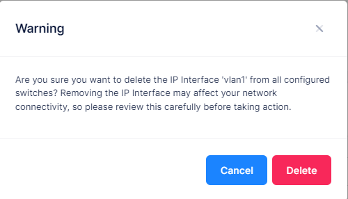
Click on Delete to confirm that you want to delete the IP Interface.
Consider the following use cases while deleting an IP Interface:
IP Interfaces with device type 'EMP' cannot be deleted.
IP Interface with device type 'Tunnel' and name 'tunnel_6to4' cannot be deleted.
IP Interfaces with device type 'Loopback' and name 'Loopback' (case sensitive for IPv4 interface and case insensitive for IPv6 interface) cannot be deleted.
View IP Interfaces
The Interface List displays basic and detailed information for all IP interfaces configured for the devices. Click on an entry in the list to view additional information about an interface.
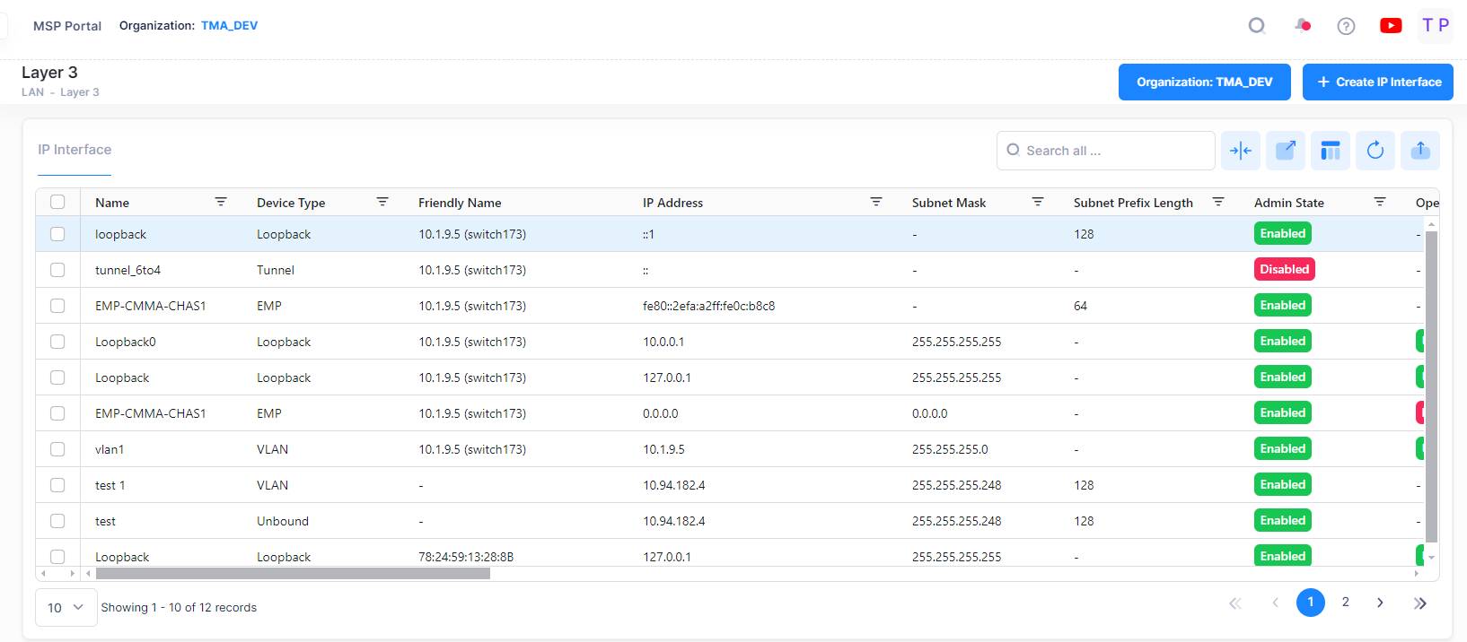
The following field values will be displayed:
Name - The user-configured interface name.
Friendly Name - The name assigned to the device is derived from the Preferred Device Naming convention specified in the user preference settings. By default, the Friendly Name is set to IP Address (System Name).
IP Address - The IP address of the IP interface.
Subnet Mask - The IP interface subnet mask value.
Subnet Prefix Length - The number that specifies the range of devices on a network and is written as a slash (/) followed by an integer between 1 and 128.
Admin State - The administrative state of the interface (Enable/Disabled).
Oper State - The operational state of the interface.
Device Type - The type of device bound to the interface:
Unbound - No device is bound to the interface.
VLAN - Associates a VLAN with the interface. You must enter the VLAN ID in the VLAN ID field.
EMP - The Ethernet Management Port is bound to the interface.
Loopback - A loopback interface configured for testing.
GRE Tunnel - A GRE Tunnel is configured for the interface. You must enter the Tunnel Source and Destination. The GRE Tunnel devices are supported only on OS10K Switches.
IP Forward - The interface forwarding status (Enabled/Disabled). A forwarding interface sends IP frames to other subnets. A "no forwarding" interface acts as a host only. It receives IP frames from other interfaces. (Default = Enabled).
MTU - The Maximum Transmission Unit size set for the interface.
VLAN ID - Interface is associated with a VLAN ID..
IP Forward - The interface forwarding status (Enabled/Disabled). A forwarding interface sends IP frames to other subnets. A "no forwarding" interface acts as a host only. It receives IP frames from other interfaces. (Default = Enabled).
IP Encapsulation - The IP interface frame encapsulation value (Ethernet 2 or SNAP). The frame encapsulation determines the framing type the interface uses when generating frames that are forwarded out VLAN ports. Select an encapsulation that matches the encapsulation of the majority of IP VLAN traffic. (Default = Ethernet 2)
VRF ID - The VRF ID. If multiple VRFs are configured on the device, the VRF ID is displayed. If none are configured, or if the feature is not available on the device, the column will display "Default", indicating that the switch is operating as a single routing instance.
Local Proxy ARP - Local Proxy ARP status (Enabled/Disabled). (Default = Disabled)
Primary Interface - If set to "True", designates the IP interface as the primary interface for the VLAN. If set to "False", the first interface bound to the VLAN becomes the primary by default. (Default = False)
Oper Reason - An explanation of the operational state. If the interface is up the field will indicate "Interface Up". If the interface is down, an explanation is displayed:
Unbound - No device is bound to the interface.
Device Down - Device bound to the interface is down.
Admin Down - The admin state of the interface is down.
No Such Device - Device does not exist.
No Router MAC - No MAC address available for the interface.
Tunnel Source Invalid - The source IP address of the tunnel is invalid.
Tunnel Destination Unreachable - The destination IP address of the tunnel is not reachable.
Router MAC - The switch MAC address assigned to the interface. Each interface assigned to the same VLAN shares the same switch MAC address.
Broadcast Address - The default broadcast address value. The default value for this field is based on the default network class range of the IP address assigned to the router interface. For example, a class A IP address, such as 10.0.0.2, has a default broadcast address of 10.255.255.255. A class C address, such as 198.181.10.2, has a default broadcast address of 198.181.10.255.
Actual Primary - Indicates if the interface is the configured and/or actual primary interface for the device (True/False).
Tunnel ID - The VPN ID used for Access Role Profile mapping. (Range = 0 - 16777215, suggested range of 64001 - 65000). If the Tunnel ID is set to "0", no GRE Key is sent.
Tunnel Source IP Address Type - The source IP address is specified in IPv4 format (x.x.x.x), where x is a decimal number from 0 to 255.
Tunnel Source IP Address - A tunnel source IP address is the interface that is used as the source address for an encapsulated GRE or IPIP packet.
Tunnel Destination IP Address Type - The destination IP address is specified in IPv4 format (x.x.x.x), where x is a decimal number from 0 to 255.
Tunnel Destination IP Address - A tunnel destination IP address is the interface that is used as the destination address for an encapsulated GRE or IPIP packet.
