Configure and Manage Layer 2 VLANs
The OmniVista Cirrus group of applications Screen displays information about all VLANs configured on managed devices; and is used to create, edit, and delete VLANS on LAN Devices. It is also used to perform certain actions on a VLAN (e.g., enable VLANs, disable VLANs, view Spanning Tree parameters, and configure an IP Router Interface).
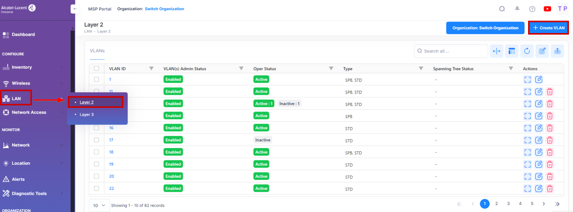
To manage the VLAN configuration, navigate to the VLANs screen by clicking on LAN > Layer 2 under the “Configure” section of the OmniVista Cirrus Menu. The VLAN List screen displays.
Creating a VLAN
To access this screen, click on Create VLAN button on top-right side of the VLANs Table.
The Create VLAN screen provides the following step-by-step process for creating a VLAN:
VLAN IDs - Each VLAN is identified by a unique number, referred to as the VLAN ID. This number is assigned at the creation time of VLAN and is not a modifiable parameter. (Range = 2 - 4094).
VLAN Configuration Template - The VLAN Configuration Screen is used to select the default VLAN IDs, assigning the default ports and modify VLAN administrative status.
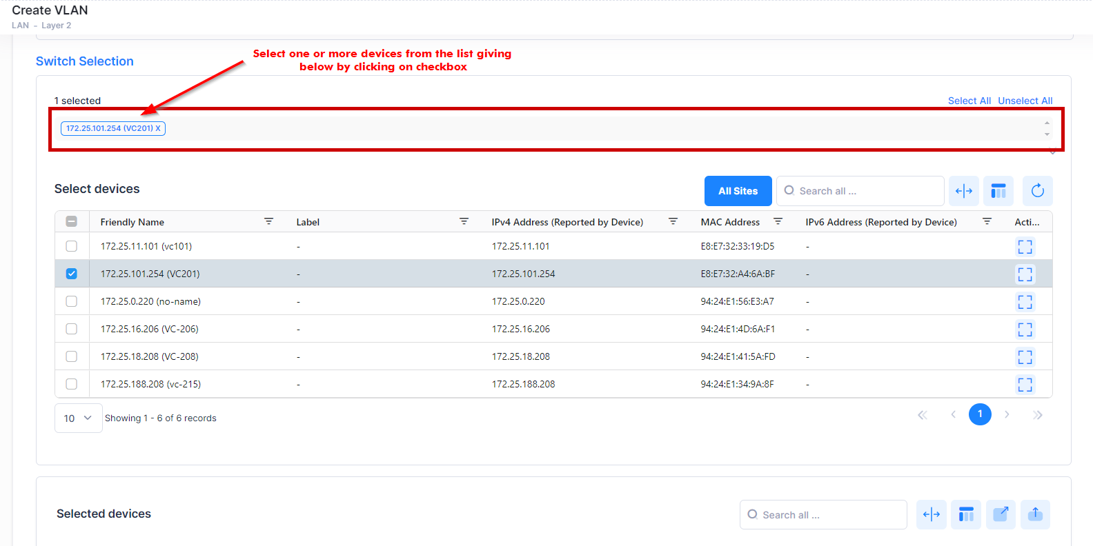
Switch Selection - Select the Switch or LAN devices from the available list to create a VLAN.
VLAN IDs
Enter the VLAN ID number (Range = 2 - 4094). To create a single VLAN, enter a single VLAN ID (e.g. 5) or enter a range of VLANs (e.g., 500-505). Note that you cannot enter a VLAN ID for a VLAN that has already been created.

VLAN Configuration template
The VLAN Configuration Template contents are applied to all selected devices, subject to availability of ports on devices. Complete the fields as described below to provide the configuration information for the VLAN:
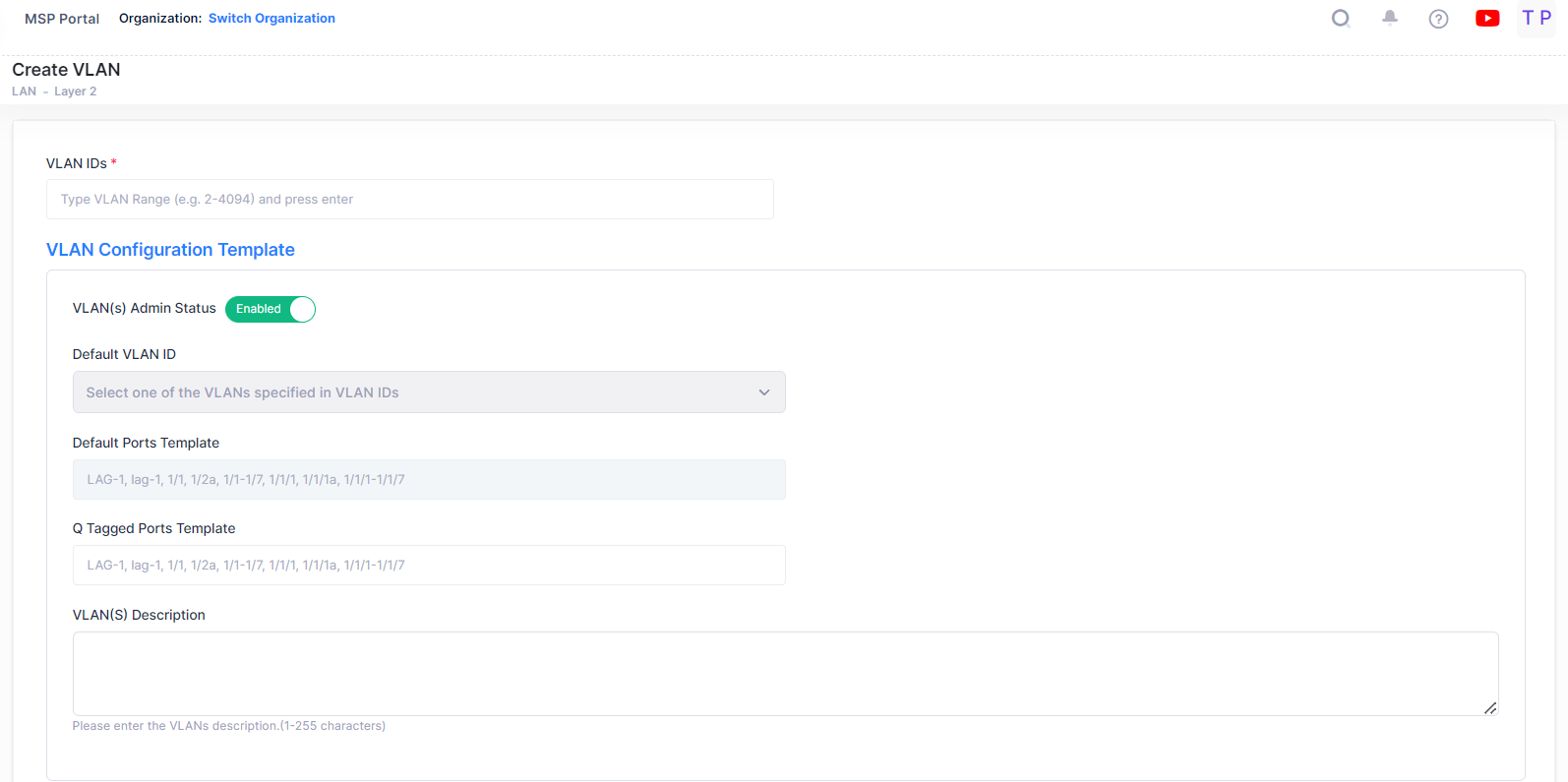
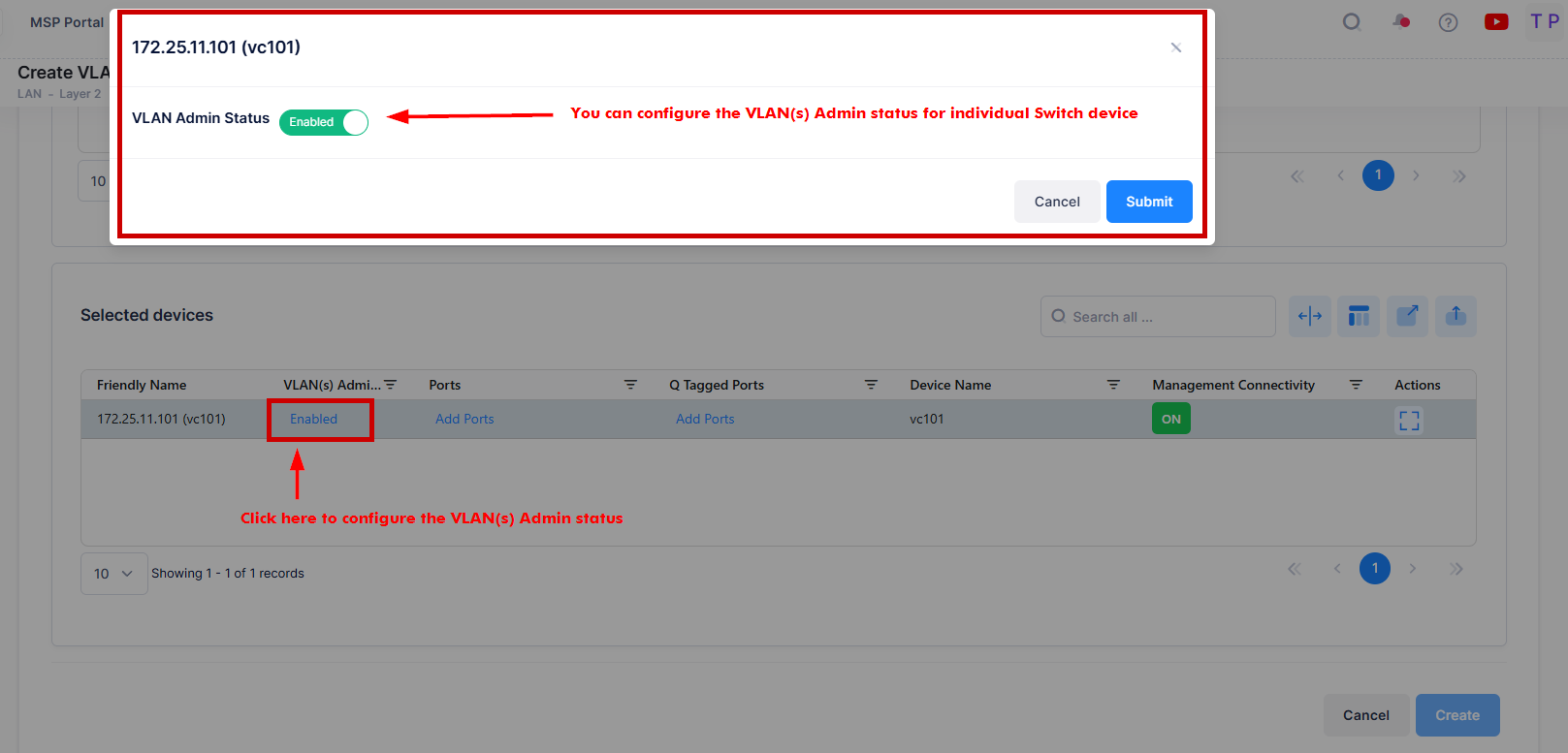
VLAN(s) Admin Status - This is the global administrative status of the VLAN (Enabled/Disabled). The configured value will be applied to all the selected switches. You can also configure the Admin status for individual switch from “Selected devices” table by clicking on the column value.
Default VLAN ID - Enter the VLAN ID of one of the VLANs. This will be the default VLAN for the configured ports.
Default Ports Template - It is used to configure default (untagged) ports for all selected devices. The configuration will be added to selected devices if the port is available on device. For example, if you enter port 1/5 as a default port when creating VLAN 100, port 1/5 will be added as a default port for all devices having port 1/5. If a selected device does not have port 1/5, the default port will not be created on the device. Ports or Link Aggregates must be entered in the format shown (e.g., LAG-1, lag-1, 1/1, 1/2a, 1/1-1/7, 1/1/1, 1/1/1a, 1/1/1-1/1/7 ).
Q Tagged Ports Template - It is used to configure Q-Tagged ports for all selected devices. The configuration will be added to selected devices if the port is available on device. For example , if you enter port 1/3 as a Q-Tagged Port when creating VLAN 100, port 1/3 will be added as a Q-Tagged port for all devices having port 1/3. If a selected device does not have port 1/3, the Q-Tagged port will not be created on the device. Ports or Link Aggregates must be entered in the format shown (e.g., LAG-1, lag-1, 1/1, 1/2a, 1/1-1/7, 1/1/1, 1/1/1a, 1/1/1-1/1/7 ).
VLAN(s) Description - Enter an optional description for the VLAN(s). If you do not enter a description, the VLAN ID is used.
Switch Selection
Select the devices from the available list to be included in the VLAN. The “Select devices” table will display only those switches which are having management connectivity “ON” state.
The selected devices will be displayed at the bottom of the section.
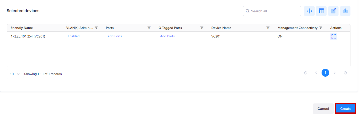
You can configure VLAN(s) Admin Status, Ports and Q Tagged Ports column for individual devices from the “Selected devices” table.
For example, you can configure the VLAN(s) Admin status for the individual device as shown below:
When you are done with the Switch Selection, click on Create button to complete the process of Creating a VLAN.
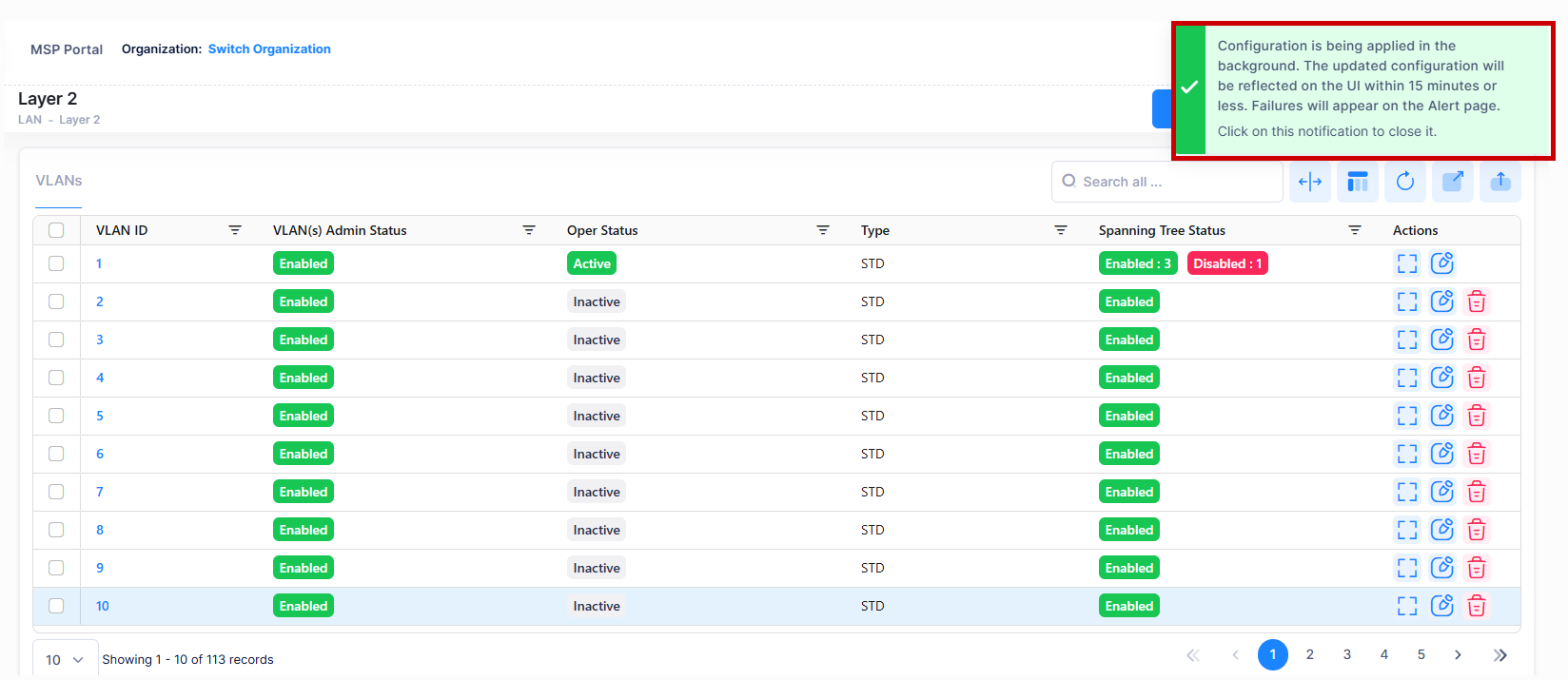
Note: If you requests for create/update/delete of VLANs from OminVista Cirrus R10 then the configuration operation is done in the background. You can view the updated configuration results after certain time interval and the following alert message appears on the screen as shown below- “Configuration is being applied in the background. The updated configuration will be reflected on the UI within 15 minutes (periodic polling) or less (immediate polling). Failure will appear on the Alerts page.”
Editing a VLAN
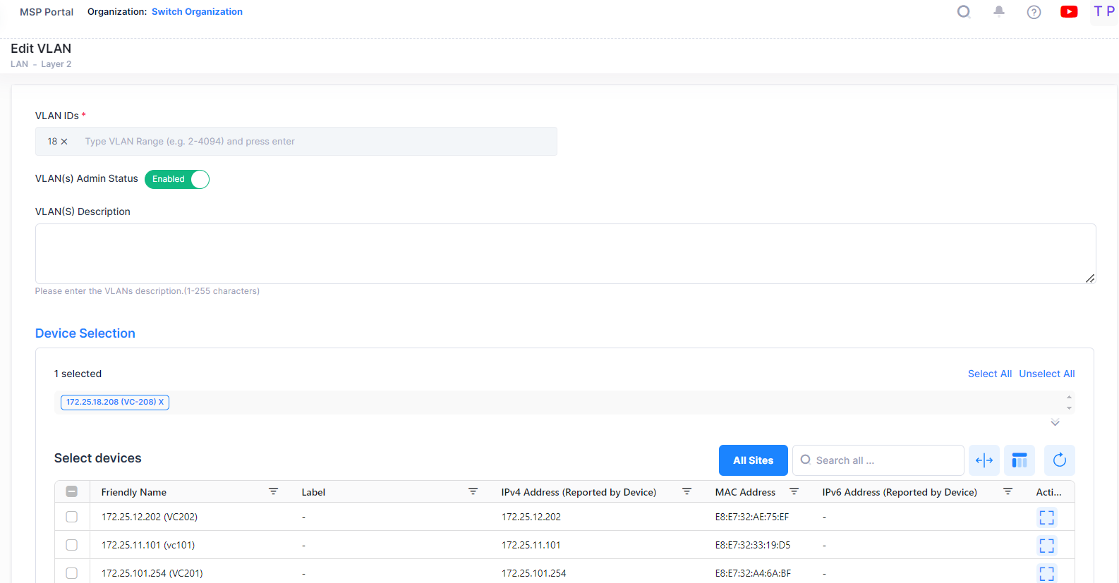
Select a VLAN ID in the VLANs List and click on the Edit icon under the “Actions” column. The Edit VLAN Information screen opens on which you can edit the VLAN Admin status and selected devices for VLAN configuration, as described above.
Consider the following while editing a VLAN:
VLAN(s) Admin Status and VLAN(s) Description are the Global attribute value, therefore, the configured value will be applied to all the selected switches. You can configure this value for individual switch from “Selected devices” table by clicking on the column value.
If the Selected device has Management connectivity status is “OFF” and the VLAN already exists for that device then it will be read only in device selection. You will not be able to modify any configuration for that device.
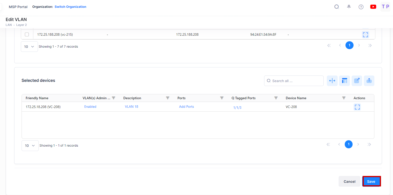
Click on Save button to save the changes.
Deleting a VLAN
To delete a VLAN, select a VLAN(s) in the VLANs Table by clicking on the checkbox next to the VLANs and use one of the following methods to select the VLAN you want to delete:
Select the VLAN to delete by clicking on the checkbox next to the VLANs, click on Actions, then select Delete from the drop-down menu.
Click on the trash can icon under the “Actions” column next to the VLAN(s) that you want to delete.

When you select the VLAN(s) you want to delete, the following confirmation prompt appears:
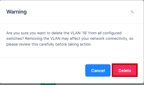
Click on Delete to confirm that you want to delete the selected VLAN(s). The VLAN will be removed from all the devices to which it was assigned.
Enabling a VLAN
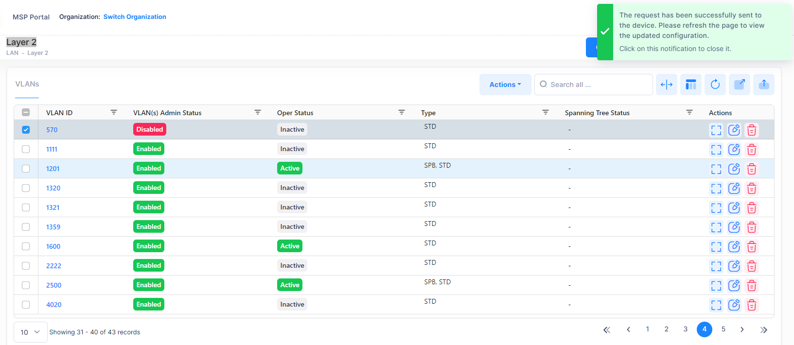
To enable a VLAN(s), select one or more VLANs in the table, click on the Actions and select Enable button.

You will get the below notification message displayed on the screen after raising request to enable a VLAN(s).
Disabling a VLAN
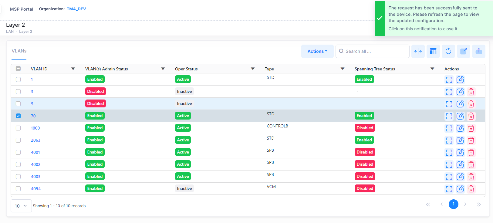
To disable a VLAN(s), select one or more VLANs in the table, click on the Actions and select Disable button.

You will get the below notification message displayed on the screen after raising request to disable a VLAN(s).
Display VLAN Details
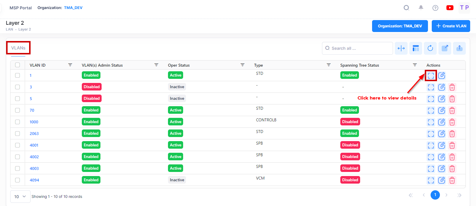
The VLAN Table displays VLANs configured on the network. The VLANs Table displays basic information about each VLAN. To view detailed information about a VLAN, select the VLAN, click on the View Details button of the VLAN Table.
Basic Information
The VLAN Table displays basic information about each VLAN.
VLAN ID - In compliance with the IEEE 802.1Q standard, each VLAN is identified by a unique number, referred to as the VLAN ID. This number is assigned at the time of creation of the VLAN and is not a modifiable parameter. When a network device packet is received on a port, the port's VLAN ID is inserted into the packet. The packet is then bridged to other ports that are assigned to the same VLAN ID. In essence, the VLAN broadcast domain is defined by a collection of ports and packets assigned to its VLAN ID. (Range = 1 - 4094)
Admin Status - The administrative status of the VLAN (Enabled/Disabled). It display the number of devices for VLAN which are Enabled and Disabled. By default, the administrative status is enabled when a VLAN is created. When a VLAN is administratively disabled, static port and dynamic mobile port assignments are retained but traffic on these ports is not forwarded. However, VLAN rules remain active and continue to classify mobile port traffic for VLAN membership.
Oper Status - The VLAN operational status (Active/Inactive). It displays the number of devices for VLAN which are active and inactive. This parameter is not modifiable; switch software determines if the VLAN is operationally active or inactive and sets the appropriate field value. A VLAN's operational status remains inactive until at least one active switch port is assigned to the VLAN and the VLAN's administrative status is enabled. This means that VLAN properties, such as Spanning Tree or router ports, also remain inactive. Ports are considered active if they are connected to an active network device. Non-active port assignments are allowed, but do not change the VLAN's operational state.
VLAN Type - The type of VLAN is determined at the time the VLAN is created (e.g., Standard, BVLAN, Control BVLAN).
Spanning Tree Status - The Spanning Tree Status (Enabled/Disabled) for the VLAN. When a VLAN is created, an 802.1D standard Spanning Tree Algorithm and Protocol (STP) instance is enabled for the VLAN by default. STP evaluates VLAN port connections to determine if there are redundant data paths between the same VLAN on other switches. If a redundant path does exist, STP determines which path to block in order to provide a loop-free network topology. In this manner, STP ensures that there is always only one active data path between any two switches (VLANs). When a change occurs, such as a path is disconnected or a path cost change, the Spanning Tree Algorithm activates the blocked path to restore the network connection.
Detailed Information
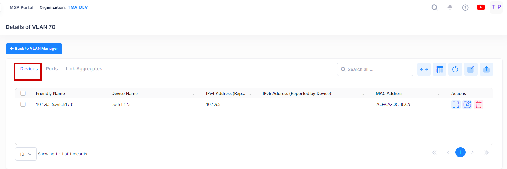
The Detail Screen provides detailed information about devices in the selected VLAN. Click on the Additional Information button or VLAN ID to display Devices, Ports, or Link Aggregates information. The following screen will appears.
Devices
For Devices, the following field values are provided:
Friendly Name - The name assigned to the device is derived from the Preferred Device Naming convention specified in the user preference settings. By default, the Friendly Name is set to IP Address (System Name).
Device Name - The user-configured name for the device.
IPv4 Address(reported by device) - The IPv4 address of the device.
IPv6 Address(reported by device) - The IPv6 address of the device(if defined).
MAC Address - The MAC address of the device.
Device Version - The version number of the device software.
Location - The physical location of the device (user-defined, up to 255 characters). If you did not specify a location the field displays "Unknown".
Management Connectivity - The following management connectivity values indicate the various stages of device connectivity with OmniVista Cirrrus.
Blank - The device is in an initial state (not yet onboarded).
On - When a device is successfully provisioned or OmniVista Cirrus receives heartbeat from the device, management connectivity transitions to “On”.
Unknown - If OmniVista Cirrus does not receive any heartbeat, the management connectivity status transitions from “On” to “Unknown”.
Off - After a certain amount of time with no heartbeat, the management connectivity status transitions from “Unknown” to “Off”.
Device Type - The device model (e.g., AOS).
VLAN ID - The VLAN ID number (e.g., VLAN 10).
VLAN Description - A text string up to 32 characters. This parameter defaults to the VLAN ID number (e.g., VLAN 10) if a description is not specified at the time the VLAN is created.
VLAN Admin Status - The administrative status of the VLAN (Enabled/Disabled).
VLAN Type - The type of VLAN is determined at the time the VLAN is created (e.g., Standard, BVLAN, Control BVLAN).
Spanning Tree Status - The Spanning Tree Status for the VLAN (Enabled/Disabled).
Oper Status - The VLAN operational status (Active/Inactive).
Router Protocol - The protocol for the VLAN virtual router port. If no router port is configured for the VLAN, then "Unknown" appears in this field. A VLAN is available for routing when a virtual router port is defined for that VLAN and at least one active port has joined the VLAN. If a VLAN does not have a router port, its ports are in essence firewalled from other VLANs.
Data displayed in each widget can be exported into a CSV, PDF or Excel sheet format. You can also switch the widgets to full-screen mode for a better display.
Port View
You can click on the Ports tab to view the Port related detail information for specific VLAN as shown below.
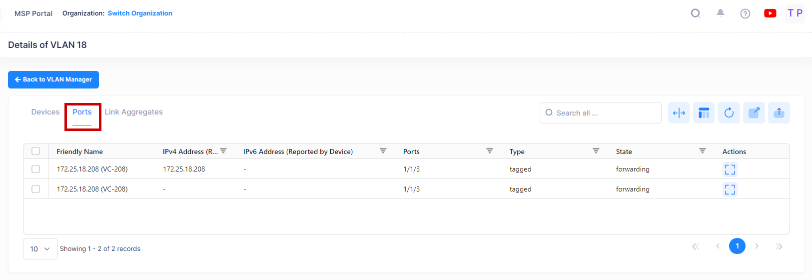
For Ports, the following field values are provided:
Friendly Name - The name assigned to the device is derived from the Preferred Device Naming convention specified in the user preference settings. By default, the Friendly Name is set to IP Address (System Name).
IPv4 Address(reported by device) - The IPv4 address of the device.
IPv6 Address(reported by device) - The IPv6 address of the device(if defined).
Port - The VLAN slot/port number.
Port Type - The Port Type parameter indicates how the port assignment to the current VLAN was made.
Default - The port is a fixed port that was statically assigned to the VLAN, which is now the configured default VLAN for the port.
Q Tagged - The port is a fixed port that was statically assigned to the VLAN using the 802.1Q tagging feature. The VLAN is a static secondary VLAN assignment for the 802.1Q tagged port.
Mobile - The port is a mobile port that was dynamically assigned to the VLAN when traffic received on the port match traffic rules defined for the VLAN. The VLAN is a dynamic secondary VLAN assignment for the mobile port.
Port State - The status of the VLAN port assignment.
Forwarding - Port is active and forwarding traffic on this VLAN.
Inactive - Port is not active (administratively disabled, down, or nothing is connected to the port).
Blocking - Port is active, but not forwarding any traffic on this VLAN.
Filtering - Mobile port traffic is filtered for the VLAN; only traffic received on the port that matches VLAN rules is forwarded. Occurs when a mobile port's VLAN is administratively disabled or the port's default VLAN status is disabled. Does not apply to fixed ports.
Data displayed in each widget can be exported into a CSV, PDF or Excel sheet format. You can also switch the widgets to full-screen mode for a better display.
Link Aggregate View
You can click on the Link Aggregates tab to view the related detail information for specific VLAN as shown below.
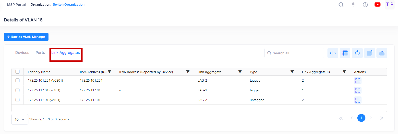
For Link Aggregates, the following field values are provided:
Friendly Name - The name assigned to the device is derived from the Preferred Device Naming convention specified in the user preference settings. By default, the Friendly Name is set to IP Address (System Name).
IPv4 Address(reported by device) - The IPv4 address of the device.
IPv6 Address(reported by device) - The IPv6 address of the device(if defined).
Link Aggregate ID- The ID of the link aggregate group of ports. This number was assigned when the aggregate was created.
Link Aggregate - An optional textual description (up to 32 characters) for the link aggregate.
Type - The Port Type parameter indicates how the port assignment to the current VLAN was made.
Default - The port is a fixed port that was statically assigned to the VLAN, which is now the configured default VLAN for the port.
Q Tagged - The port is a fixed port that was statically assigned to the VLAN using the 802.1Q tagging feature. The VLAN is a static secondary VLAN assignment for the 802.1Q tagged port.
Mobile - The port is a mobile port that was dynamically assigned to the VLAN when traffic received on the port match traffic rules defined for the VLAN. The VLAN is a dynamic secondary VLAN assignment for the mobile port.
Edit the VLAN Configuration from VLAN Details View
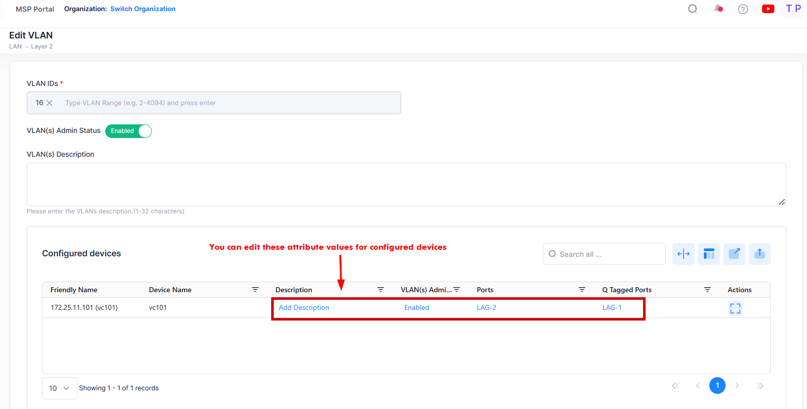
Select the device in the Devices List and click on the Edit icon under the “Actions” column to modify or update the VLAN configuration on Switch devices from the VLAN Details screen.

The Edit VLAN Information screen opens on which you can edit the VLAN(s) Admin status, VLAN(s) Description, Ports and Q tagged Ports for VLAN configuration on configured devices as shown below.
Consider the following while editing the VLAN configuration on selected devices:
You cannot modify the VLAN ID(s) of the devices.
You cannot add new devices to existing VLAN(s). Use Global VLAN Edit option from VLANs Main Summary screen to add new device to existing VLAN(s).
You can modify or update the ports and Q tagged ports value.
VLAN(s) Admin Status and VLAN(s) Description are the Global attribute value, therefore, the configured value will be applied to all the selected switches. You can configure this value for individual switch from “Selected devices” table by clicking on the column value.
Click on Save button to save the changes.
Viewing Spanning Tree
The Spanning Tree Screen is used to view Spanning Tree configuration information for devices in a VLAN, and to modify Spanning Tree Bridge or Port Parameters. To view/edit Spanning Tree information for a VLAN, select the VLAN in the VLANs Table, then select Spanning Tree from the Actions drop-down menu at the top of the screen.
Data displayed in each widget can be exported into a CSV, PDF or Excel sheet format. You can also switch the widgets to full-screen mode for a better display.

By default, a Summary view is displayed. Click on the Bridge or Port tab at the top of the screen to view bridge or port information as shown below.
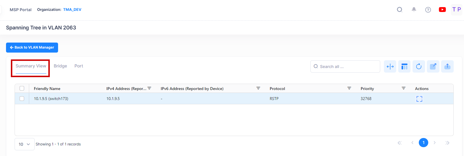
Summary View
The Summary View displays a summary of the Spanning Tree information for devices in the selected VLAN. The following field values are displayed:
Friendly Name - The name assigned to the device is derived from the Preferred Device Naming convention specified in the user preference settings. By default, the Friendly Name is set to IP Address (System Name).
IPv4 Address(reported by device) - The IPv4 address of the device.
IPv6 Address(reported by device) - The IPv6 address of the device(if defined).
Protocol - The VLAN spanning tree algorithm protocol. The algorithm determines the state and role of a port within the spanning tree topology:
STP (802.1D) - Standard Spanning Tree Algorithm and Protocol (Default).
RSTP (802.1W) - Rapid Spanning Tree Algorithm and Protocol. RSTP is based on the 802.1D standard algorithm and is designed to provide quick recovery in the event of a link, port or device failure.
MSTP (802.1S) - Multiple Spanning Tree Protocol. MSTP is an enhancement to 802.1Q Common Spanning Tree Instance (CST). When the switch is running in Flat Mode, a single Spanning Tree instance is applied across all VLAN port connections. MSTP allows the configuration of Multiple Spanning Tree Instances (MSTI) in addition to the CST instance. Each MSTI is mapped to a set of VLANs. As a result, Flat Mode can now support the forwarding of VLAN traffic over separate data paths. Note that MSTP in VLAN spanning tree view is only displayed for Instance 0 under VLAN 1. None of the other instances will be displayed.
Priority - The bridge priority value (0 - 65535) for the VLAN. The lower the number, the higher the priority value. The bridge priority value is used by the spanning tree algorithm to determine which VLAN should serve as the root of the spanning tree. (Default = 32768)
Maximum Age - The amount of time, in seconds, that spanning tree information learned from BPDUs received on VLAN ports is retained. When this information has aged beyond the maximum age value, the information is discarded. (Range = ( 6- 40, Default = 20)
Path Cost - The cost of the path to the root for this Spanning Tree instance.
Mode - The Spanning Tree operating mode for the switch:
Flat Mode (Single Spanning Tree) - The Spanning Tree Algorithm is applied across all VLANs. For example, if a port belonging to VLAN 10 and a port belonging to VLAN 20 both connect to the same switch, then Spanning Tree Algorithm will block one of these ports.
1x1 (One Spanning Tree per VLAN) - A single Spanning Tree instance is enabled for each VLAN configured on the switch. For example, if there are five VLANs configured on the switch, then there are five separate Spanning Tree instances. In essence, a VLAN is a virtual bridge in that it will have its own bridge ID and configurable STP parameters, such as protocol, priority, hello time, max age and forward delay. Note: By default, the Spanning Tree operating mode is set to One Spanning Tree Per VLAN (available only on AOS switch platforms).
Bridge ID - The bridge identifier for this Spanning Tree instance. Consists of the bridge priority value (in hex) concatenated with the bridge MAC address.
Root ID- The bridge identifier of the root of the spanning tree as determined by the Spanning Tree Algorithm and Protocol.
Time Since Last Topology Change - The amount of time, in hundredths of a second, since the last topology change was detected by this Spanning Tree instance.
Total Topology Change - The number of topology changes detected by this spanning tree instance since the management entity was last reset or initialized.
Root Port - The port that offers the lowest cost path from this bridge to the root bridge for this Spanning Tree instance.
Next Best Root Cost - The cost of the next best root port for this Spanning Tree instance.
Next Best Root Port - The port that offers the next best (second lowest) cost path to the root bridge for this Spanning Tree instance.
Network Maximum Age - The Maximum Age time value for the root bridge.
Network Hello Time - The Hello Time value for the root bridge.
Network Hold Time - The amount of time, in hundredths of a second, in which this spanning tree instance can transmit no more than two Configuration Bridge Protocol Data Units (BPDU).
Network Forward Delay - The forward delay time value for the root bridge.
Bridge View
The Bridge View List displays a Spanning Tree bridge information for devices in the selected VLAN. To access the Bridge View click on the Bridge tab in the VLAN Manager Spanning Tree screen as shown below.
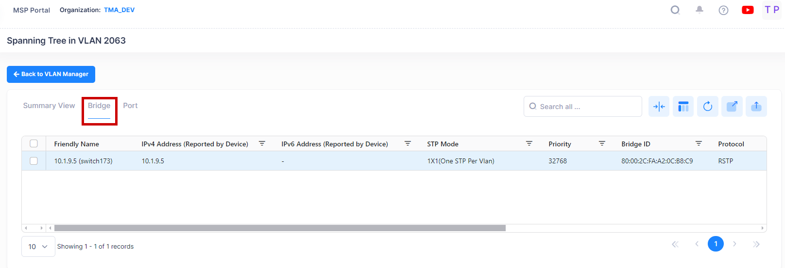
The following field values are displayed:
Friendly Name - The name assigned to the device is derived from the Preferred Device Naming convention specified in the user preference settings. By default, the Friendly Name is set to IP Address (System Name).
IPv4 Address(reported by device) - The IPv4 address of the device.
IPv6 Address(reported by device) - The IPv6 address of the device(if defined).
Protocol - The VLAN spanning tree algorithm protocol. The algorithm determines the state and role of a port within the spanning tree topology:
STP (802.1D) - Standard Spanning Tree Algorithm and Protocol (Default).
RSTP (802.1W) - Rapid Spanning Tree Algorithm and Protocol. RSTP is based on the 802.1D standard algorithm and is designed to provide quick recovery in the event of a link, port or device failure.
MSTP (802.1S) - Multiple Spanning Tree Protocol. MSTP is an enhancement to 802.1Q Common Spanning Tree Instance (CST). When the switch is running in Flat Mode, a single Spanning Tree instance is applied across all VLAN port connections. MSTP allows the configuration of Multiple Spanning Tree Instances (MSTI) in addition to the CST instance. Each MSTI is mapped to a set of VLANs. As a result, Flat Mode can now support the forwarding of VLAN traffic over separate data paths. Note that MSTP in VLAN spanning tree view is only displayed for Instance 0 under VLAN 1. None of the other instances will be displayed.
Priority - The bridge priority value (0 - 65535) for the VLAN. The lower the number, the higher the priority value. The bridge priority value is used by the spanning tree algorithm to determine which VLAN should serve as the root of the spanning tree. (Default = 32768)
STP Mode - The Spanning Tree operating mode for the switch:
Flat Mode (Single Spanning Tree) - The Spanning Tree Algorithm is applied across all VLANs. For example, if a port belonging to VLAN 10 and a port belonging to VLAN 20 both connect to the same switch, then Spanning Tree Algorithm will block one of these ports.
1x1 (One Spanning Tree per VLAN) - A single Spanning Tree instance is enabled for each VLAN configured on the switch. For example, if there are five VLANs configured on the switch, then there are five separate Spanning Tree instances. In essence, a VLAN is a virtual bridge in that it will have its own bridge ID and configurable STP parameters, such as protocol, priority, hello time, max age and forward delay. Note: By default, the Spanning Tree operating mode is set to One Spanning Tree Per VLAN (available only on AOS switch platforms).
Bridge ID - The bridge identifier for this Spanning Tree instance. Consists of the bridge priority value (in hex) concatenated with the bridge MAC address.
Network Maximum Age - The amount of time, in seconds, that spanning tree information learned from BPDUs received on VLAN ports is retained. When this information has aged beyond the maximum age value, the information is discarded. (Range = ( 6- 40, Default = 20)
Network Hello Time -The Hello Time value for the root bridge.
Network Forward Delay -The forward delay time value for the root bridge.
Port View
The Port View List displays a Spanning Tree port information for devices in the selected VLAN. To access the Port View click on the Port tab in the VLAN Manager Spanning Tree screen as shown below.
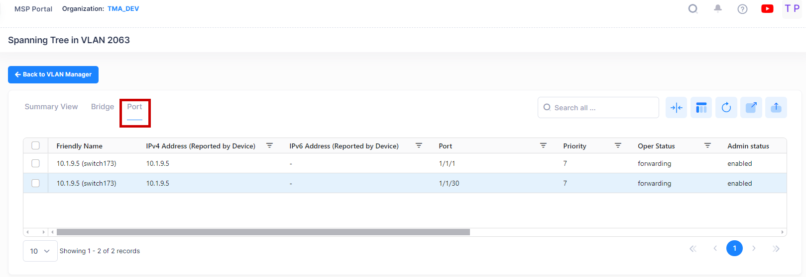
The following field values are displayed:
Friendly Name - The name assigned to the device is derived from the Preferred Device Naming convention specified in the user preference settings. By default, the Friendly Name is set to IP Address (System Name).
IPv4 Address(reported by device) - The IPv4 address of the device.
IPv6 Address(reported by device) - The IPv6 address of the device(if defined).
Port - The slot/port number.
Priority -The port priority value for the VLAN. The lower the number, the higher the priority value. The port priority is used to determine which port offers the best path to the root when multiple paths have the same path cost. If the priority values are the same for all ports in the path, then the port with the lowest physical switch port number is selected. (Range = (0 - 15, Default = 7)
Oper Status - The operational state of the port as determined by the spanning tree algorithm:
Disabled - Physical port is down or administratively disabled.
Blocking or Discarding - Port does not transmit or receive data to prevent a network loop.
Listening - Port is preparing to transmit data.
Learning - Port is learning MAC addresses seen on the port.
Forwarding - Port is transmitting and receiving data.
Admin Status - The Spanning Tree status for the port (Enabled/Disabled). If disabled, the port state is set to forwarding for the VLAN Spanning Tree instance. This status value, however, is ignored if Spanning Tree is disabled for the associated VLAN. By default, Spanning Tree is enabled on all switch ports.
Path Cost - The path cost value for the port. This value specifies the contribution of a port to the path cost towards the root bridge that includes the port. If the path cost is set to 0, then a default value based on link speed is used. (Range = ( 0 - 65535).
Manual Mode - The mode used for managing the port's state:
Blocking or Forwarding (Manually Set) - If the port state is manually set to Blocking or Forwarding, the port remains in that state until it is changed and does not participate in the spanning tree algorithm.
No (Dynamic) - Dynamic mode defers configuration of the port state to the spanning tree algorithm. By default, this parameter is set to No (Dynamic).
Admin Connection - The port's administratively set connection type. This parameter is used by the 802.1w Rapid Spanning Tree Protocol (RSTP) to determine if a port is eligible for rapid transition to the forwarding state.
No Point to Point - Port connects to multiple switches.
Point to Point - Port connects directly to another switch.
Auto Point to Point - Connection type is automatically defined to No Point to Point or Point to Point based on the port's operational status. (Default)
Edge Port - Port is at the edge of a bridged LAN, does not receive BPDU, and has only one MAC address learned. Edge ports, however, will operationally revert to a No Point to Point connection type if a BPDU is received on the port.
Port Role - The role of the port for this Spanning Tree instance (e.g., Root, Designated, Alternate, Backup).
Oper Connection - The operational connection type for the port:
No Point to Point - Port connects to multiple switches.
Point to Point - Port connects directly to another switch.
Auto Point to Point - Connection type is automatically defined to No Point to Point or Point to Point based on the port's operational status. (Default)
Edge Port - Port is at the edge of a bridged LAN, does not receive BPDU, and has only one MAC address learned. Edge ports, however, will operationally revert to a No Point to Point connection type if a BPDU is received on the port.
Non-Significant - Port is inactive.
Editing an STP Configuration
You can edit Spanning Tree Bridge or Port parameters on switches in a VLAN. Select the VLAN in the VLANs Table, then select Spanning Tree from the Actions drop-down menu at the top of the screen to bring up the Spanning Tree Summary View Table for the VLAN.
Click on the Bridge or Port tab at the top of the table to bring up the Bridge or Port Table. Select a switch/port in a table then click on the Edit icon.
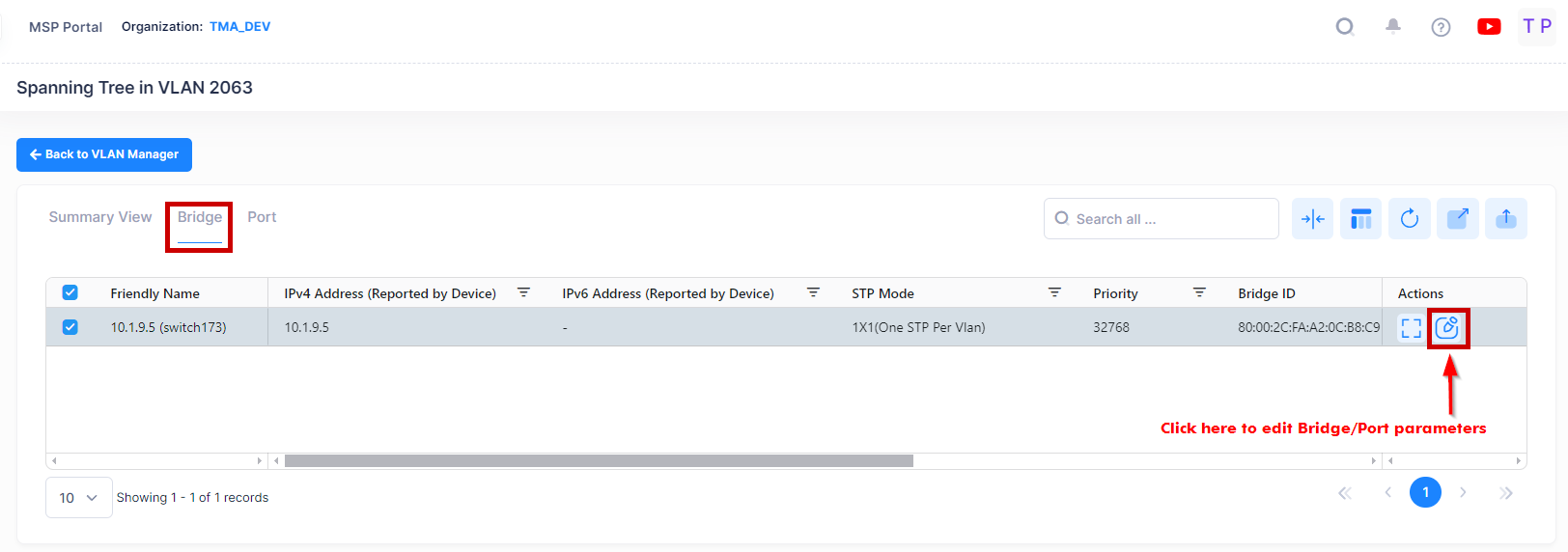
The following screen will appears:
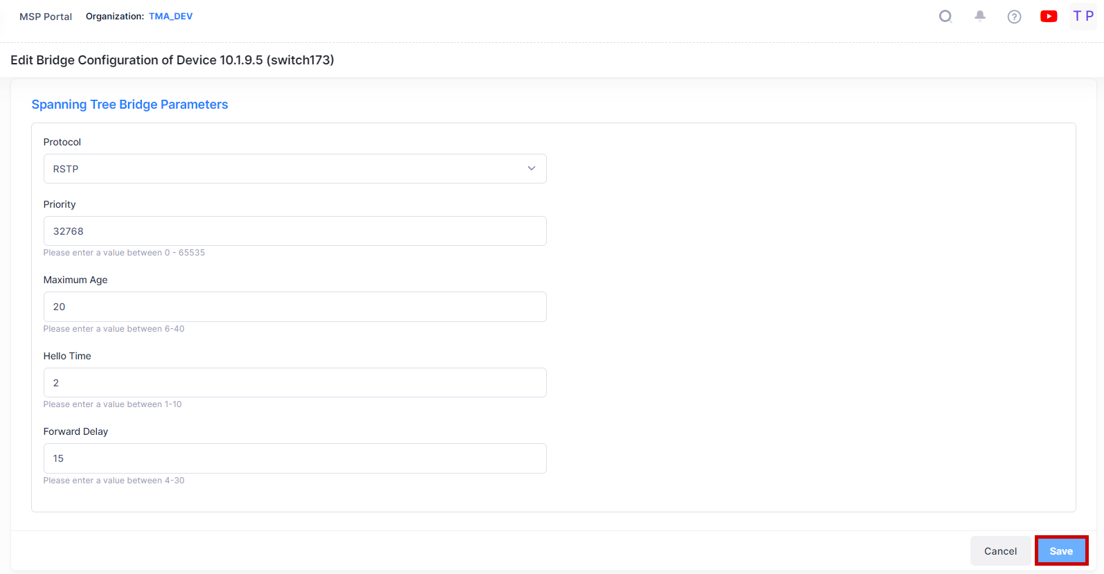
Edit the Bridge or Port parameters as described above and click on the Save button. Repeat to edit additional Bridge or Port parameters.
Note: Spanning Tree software is active on all switches by default. As a result, a loop-free network topology is automatically calculated based on default Spanning Tree switch, VLAN (bridge), and port parameter values. It is only necessary to configure Spanning Tree bridge parameters to change how the topology is calculated and maintained.
IP Router
Network device traffic is bridged (switched) at the Layer 2 level between ports that are assigned to the same VLAN. However, if a device needs to communicate with another device that belongs to a different VLAN, you must configure an IP router interface on a device in the VLAN to enable Layer 3 routing to transmit traffic between VLANs.
A VLAN is available for routing when at least one IP router interface is defined for that VLAN and at least one active port is associated with the VLAN. If a VLAN does not have a router interface, the ports associated with that VLAN are in essence firewalled from other VLANs.
The IP Router Screen in the VLANs application is used to view and configure IP Routers on a VLAN. To configure an IP router for a VLAN, select the VLAN in the VLANs Table, then select IP Router from the Actions drop-down menu at the top of the screen.

The IP Router Screen will appear:
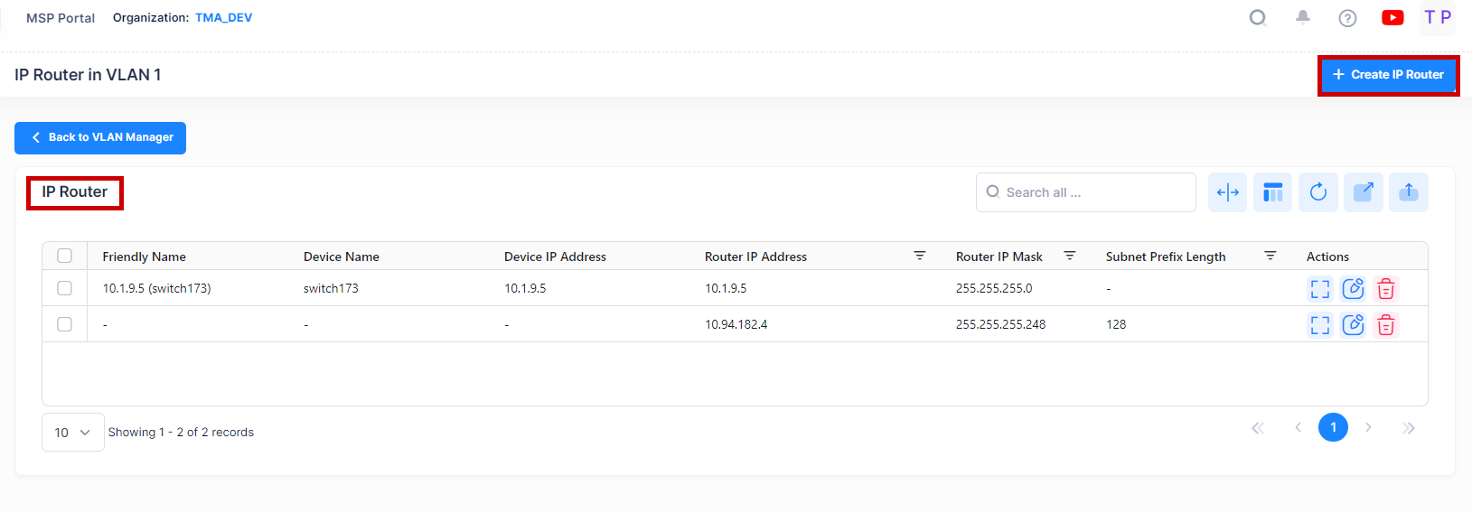
The VLAN Manager IP Router Screen displays all configured IP router interfaces for the selected VLAN. It is also used to create, edit, and delete IP router interfaces on devices in the VLAN.
Viewing IP Router Interfaces
The Router Screen displays all configured IP router interfaces for the selected VLAN. The fields are defined below.
Device Name - The user-configured name for the device on which the interface is configured.
Friendly Name - The name assigned to the device is derived from the Preferred Device Naming convention specified in the user preference settings. By default, the Friendly Name is set to IP Address (System Name).
Device IP Address - The IP address of the device.
Router IP Address - The IP address of the IP router interface.
Router IP Mask - The IP router subnet mask value. The default value for this field is based on which network class range the IP address falls within; Class A, B, or C. (255.0.0.0, 255.255.0.0, or 255.255.255.0).
Subnet Prefix Length - The number that specifies the range of devices on a network and is written as a slash (/) followed by an integer between 1 and 128.
IP Encapsulation - The IP router interface frame encapsulation value (Ethernet 2 or SNAP). The frame encapsulation determines the framing type the router interface uses when generating frames that are forwarded out VLAN ports. Select an encapsulation that matches the encapsulation of the majority of IP VLAN traffic. (Default = Ethernet 2)
IP Forwarding - The router interface forwarding status (Enabled/Disabled). A forwarding router interface sends IP frames to other subnets. A "no forwarding" router interface acts as a host only. It receives IP frames from other router interfaces. (Default = Enabled).
Interface Name - The user-defined interface name (up to 20 characters).
VRF ID - The VRF ID. If multiple VRFs are configured on the device, the VRF ID is displayed. If none are configured, or if the feature is not available on the device, the column will display "Default", indicating that the switch is operating as a single routing instance.
Creating an IP Routing Interface
Click on the Create IP Router tab to create an IP router interface on a device in a VLAN. The following create screen appears:
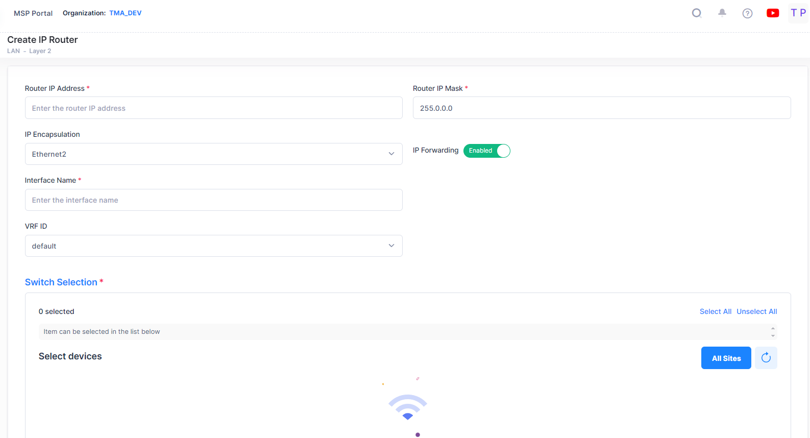
Complete the fields as described below, then click on the Create button.
Router IP Address - The IP address of the IP router interface. Router interface IP addresses must be unique. You cannot have two router interfaces with the same IP address.
Router IP Mask - The IP router subnet mask value. The default value for this field is based on which network class range the IP address falls within; Class A, B, or C. (255.0.0.0, 255.255.0.0, or 255.255.255.0).
IP Encapsulation - The IP router interface frame encapsulation value (Ethernet 2 or SNAP). The frame encapsulation determines the framing type the router interface uses when generating frames that are forwarded out VLAN ports. Select an encapsulation that matches the encapsulation of the majority of IP VLAN traffic. (Default = Ethernet 2)
IP Forwarding - The router interface forwarding status (Enabled/Disabled). A forwarding router interface sends IP frames to other subnets. A "no forwarding" router interface acts as a host only. It receives IP frames from other router interfaces. (Default = Enabled).
Interface Name - The user-defined interface name (up to 32 characters).
VRF ID - The VRF ID. If configured, select a VRF from the drop-down menu to assign the interface to a configured VRF instance (by default all interfaces are assigned to the Default VRF). You can assign a new interface to a VRF; however, you cannot edit the VRF ID of an existing interface. If the feature is not available on the device, the column will display "Default", indicating that the switch is operating as a single routing instance.
Switch Selection - Select a Switch device from the available list of devices that are members of the VLAN by clicking on the checkbox next to the Select devices list. Select the device(s) on which you want to create an IP router interface and click on Create button.
Note: When you requests for create/update/delete of an IP Router Interface from OminVista Cirrus R10, the configuration operation is done in the background. You can view the updated configuration results after certain time interval and the following alert message appears on the screen as shown below.

Editing an IP Router Interface
To edit an IP router interface on a device, select the interface in the IP Router Table and click on the Edit icon.

Edit any fields as described above and click on the Save button.
You cannot edit the Interface Name or VRF fields.
Deleting an IP Router Interface
To delete an IP router interface, select the interface in the IP Router Table, then click on the Delete icon as shown below.

When you select the IP Router Interface you want to delete, the following confirmation prompt appears:
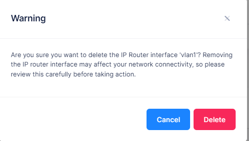
Click on Delete to confirm that you want to delete the selected IP Router Interface. The IP Router Interface will be removed from all the devices to which it was assigned.
