The Topology feature in OmniVista provides a unified, visual representation of the network, allowing administrators to understand physical connectivity, logical services, and wireless coverage from a single entry point.
Topology is view-based, each view highlights a specific abstraction layer of the network to support faster troubleshooting and operational insight.
OmniVista opens the Topology page in a default view, from which you can seamlessly switch between available views.
Devices must first be added to the Device Catalog and licensed before they are displayed in Topology. See the Device Catalog online help for more information.
The Topology information is displayed based on the site selected. Select the site using the Site: button on the top right corner of the screen.
The Topology Map is displayed for the selected site, only if the topology information is available for the site.
The Topology page lets you switch between these views:
-
Network: Displays the physical topology of switches, access points, and their connections.
-
Geography: Displays Wi-Fi heatmap, site location and device distribution on a map.
Each view focuses on a specific aspect of the network while maintaining a consistent interaction model.
Network
From the Network View you can choose the topology view for the following Network Services:
-
Physical: Displays the physical topology of switches and access points, including their physical connections.
-
SPB: Displays Shortest Path Bridging (SPB) logical services and their interconnections.
-
VLAN: Displays VLAN-based logical connectivity across the network.

Select a service from the Network Services drop-down menu to display its Topology Map.
When a service is selected, devices configured for it appear active on the topology map, while others are grayed out.
To explore more on the Topology Map, refer Topology Maps.
Physical Topology
The Physical view provides a real-time, graphical representation (Topology map) of the network’s physical topology.
-
This view shows:
-
Managed switches and access points
-
The physical links between them
-
-
Devices are displayed as icons with color-coded status indicators that reflect:
-
Connectivity – whether the device is reachable/online and how healthy its connection is.
-
Trap severity – the seriousness of any alerts or events reported by the device (for example, warning or critical issues).
-
-
Links visually represent the operational state of physical connections.
-
From this view, you can:
-
Pan and zoom
-
Adjust the layout
-
Select individual devices to view device details
-
-
Device details include:
-
Model
-
Software version
-
IP/MAC address
-
Recent events
-
-
The Physical view is primarily used to:
-
Understand hardware connectivity
-
Verify link status
-
Quickly identify devices or connections requiring attention.
-
Refer Topology Maps for detailed information on using the UI options.
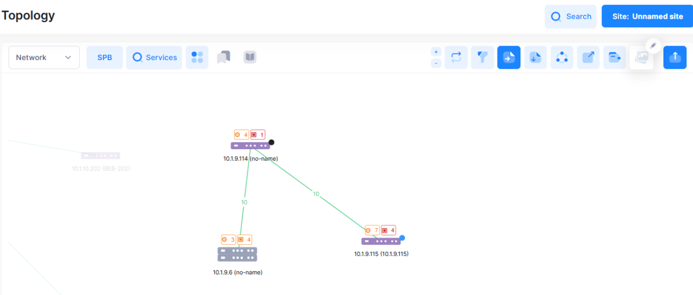
SPB Service Topology
The SPB view provides a logical, service‑oriented visualization of Shortest Path Bridging (SPB) in the network.
This view focuses on how SPB services are established and transported across switches, rather than on physical cabling.
-
From this view, you can:
-
Switch to SPB Services.
-
Interactively explore SPB configuration and operational details.
-
-
Service-level information is presented through the Services Table, including:
-
Service name
-
Admin/operation state
-
ISID
-
BVLAN
-
VLAN translation
-
SAP/SDP counts
-
Multicast mode
-
Statistics
-
-
Access-related information is presented through the Access Interfaces Table, including:
-
Access port configuration
-
Link status
-
L2 profiles
-
VLAN translation
-
UNP templates
-
SAP counts
-
-
You can also:
-
Drill down into SDP and SAP details per selected service.
-
View customer VLAN information on SAP-connected Layer‑2 switches via link hover.
-
Visualize SPT (Shortest Path Tree) links between nodes for a selected BVLAN, with highlighted paths and contextual link information.
-
The SPB view provides a logical, service‑oriented visualization of Shortest Path Bridging (SPB) in the network.
-
It focuses on how SPB services are established and transported across switches, rather than on physical cabling.
-
-
Refer Topology Maps for detailed information on using the UI options.
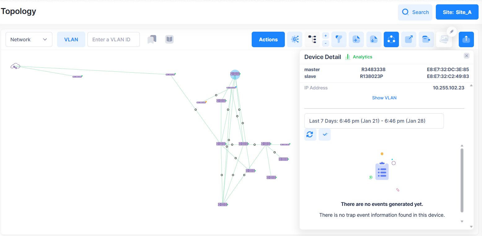
VLAN Service Topology
The VLAN view offers a logical visualization of VLAN services across the network.
You can use this view to see how individual VLANs are configured and connected between devices.
-
When the VLAN view is selected:
-
A VLAN selector appears.
-
You can choose a VLAN from the list of known VLANs or enter a specific VLAN ID.
-
All non-relevant devices and links are grayed out to maintain focus.
-
-
Devices that have the selected VLAN configured are:
-
Highlighted using a VLAN-specific color code.
-
-
Links between devices are highlighted only when:
-
Both ends have the VLAN configured on the connecting ports, and
-
Both sides share the same configuration type (both tagged or both untagged).
-
-
Hovering over or selecting a device displays an information panel showing:
-
Switch type
-
Device-friendly name
-
IP address
-
Serial number
-
List of VLANs configured on the relevant ports (tagged and untagged)
-
-
Hovering over or selecting a link display:
-
VLAN information limited to the VLANs consistently configured on both sides of the link.
-
Refer Topology Maps for detailed information on using the UI options.
Topology Maps
The Topology application provides a network overview and enables viewing and configuring network devices. These functions are detailed in the following sections:
Working with Topology Maps
This section details the Topology Map view. In this view, you can view device and link information, customize the map background image, change the map layout, and perform device actions.
Viewing Map Information
Topology Maps provide a visual representation of the network. The administrative status of the device or link is indicated by color, and detailed information can be displayed by clicking on a device or link.
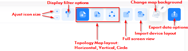
You can change the Topology Map view, layout, background, and import or export Map information using the following icons located at the top-right corner of the screen.
To save a Topology Map view, you can take a snapshot and/or export the Map layout to a text (.txt) or .svg file.
Devices
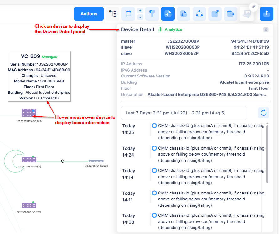
Each device type is displayed with an icon. Hover the mouse over a device to display basic information. Click on a device to open the Device Detail panel and view detailed information about the device.
The status of a device is indicated by the following color coding of the small dot in the upper-right corner of the device icon and/or by the icon itself. The dot color to use for the device status is based on the specified color theme for trap severity levels configured in the User Preference settings for Appearance.
-
Green - Device connectivity is up and there are no trap notifications.
-
Orange - Device connectivity is unknown or warning/major trap notifications received from the device.
-
Red - Device connectivity is up with critical trap notifications received.
-
Blue - Device connectivity is up with minor or normal trap notifications.
-
No Circle - No management connectivity information or trap notifications received from the device.
-
Solid-Grey Device Icon - Device connectivity is down with no trap notifications.
-
Generic Icon - The device is unmanaged by OmniVista.

Note that the trap event notification status is only displayed if traps have been configured on the device.
Links
Links between devices are displayed as a single line, whether there is a single link or multiple links.
-
Green - Link is up. If there are multiple links, Green indicates all of the links are up.
-
Red - Link is down. If there are multiple links, Red indicates all of the links are down.
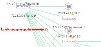
Aggregate links are displayed as a solid line with a black circle.
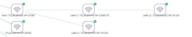
AP Mesh networks are displayed with a dashed line between AP Wi-Fi icons that are part of the Mesh network configuration.
A loop next to a switch indicates a loopback port link on the switch.
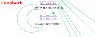
You can hide loopback links on the Topology Map by clicking on the Show Filter Options icon in the top-right corner of the screen. Click the icon again to display the loopback links.
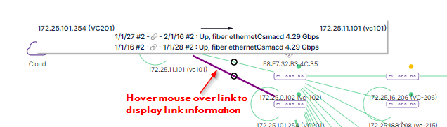
Displaying Link Information
To display link information, move the mouse over the link until the pointer turns into a finger. Link information will be displayed as shown below. Information for all links is displayed.
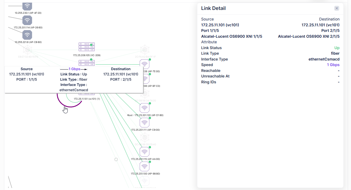
You can also click on a link to display detailed link information. Move the mouse over the link until the pointer turns into a finger and click. The link is highlighted and link information is displayed in the Link Detail panel as shown below.
Customizing Maps
You can change the Topology Map display, layout, and background image.
Adjusting the Size of Device Icons on the Topology Map
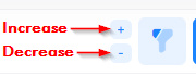
The size of the device icons is adjustable to make the icons smaller or larger on the Topology Map. Decreasing the size of the device icons can help to provide a clean, compact view of a large network topology.
To increase or decrease the size of device icons, click on the plus (+) or minus (-) sign in the top-right corner of the screen.
Filtering the Topology Map Display
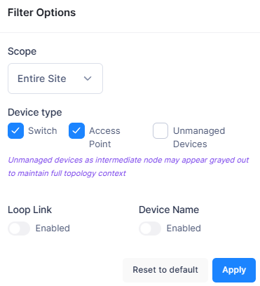
You can specify which devices that you want to include in the Topology Map by clicking on the Show Filter Options icon in the top-right corner of the screen. Select the display options from the drop-down menu as described below.
-
Scope - Select Entire Site (the default), Building, or Floor.
-
Entire Site - Displays all devices associated with the current Organization Site.
-
Building - Displays all devices associated with a specific Building. Select the Building to include from the “Select Entity” drop-down list.
-
Floor - Displays all devices associated with a specific Floor. Select the Floor to include from the “Select Entity” drop-down list.
-
-
Device type - Select the type of devices that you want to include in the Topology Map (Switch, Access Point, Unmanaged Devices). Note that Unmanaged Devices are not selected by default. However, if an unmanaged device is an intermediate node, it may still appear grayed out in the Topology Map.
-
Loop Link - Enable or disable (the default) the display of loopback link ports on the Topology Map.
-
Device Name - Enable or disable (the default) the display of device names next to Topology Map devices.
When you are finished selecting the Filter Options for the Topology Map, click Apply. The Map display will change based on the options you selected.
Changing the Map Layout
To change the basic layout of the Topology Map, click on the Horizontal, Vertical, or Circle icon in the top-right corner of the screen.
-
Horizontal - Displays devices in a horizontal pattern.
-
Vertical - Displays devices in a vertical pattern.
-
Circle - Displays devices in a spiral pattern.
You can also change the layout of a Topology Map using any of the following methods:
-
Select a device and drag it to a new location on the Map. Press Shift and click to select multiple devices.
-
Zoom in or out on a Map using the mouse scroll wheel.
-
Move an entire Map on the screen by clicking anywhere outside the map and dragging the Map to a new location on the screen.
Changing the Background Image
You can change the Topology Map background image by clicking on the Change Background icon in the top-right corner of the screen. When you click on this icon, you are prompted to locate and upload an image file that you want to set as the background image for your Topology Map.
After the selected image is uploaded, click on the checkmark in the top corner of the Change Background icon to update the background of the Topology Map. The checkmark will then disappear from the icon.
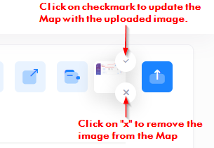
To remove a background image, click on the “x” in the bottom corner of the Change Background icon.
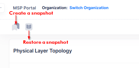
Creating a Snapshot of the Topology Map
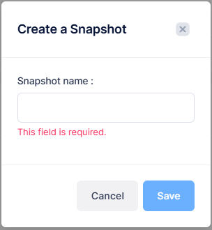
To create a snapshot of your Topology Map nodes, devices, and client positions, click on the Create a Snapshot icon located next in the top-left corner of the screen. A Create a Snapshot window will open. Enter a name to assign to the snapshot file, then click on Save.
The Topology Map snapshot you created now appears next to the Restore Snapshot icon.

If you make any changes to the Topology Map layout after the snapshot is done, the changes are not automatically updated in the existing snapshot file. You have the following two options to save the changes:
-
Update the current snapshot positions by clicking on the checkmark next to the snapshot name. The checkmark indicates that changes were made after the snapshot was saved.

-
Create another snapshot for the updated Topology Map.
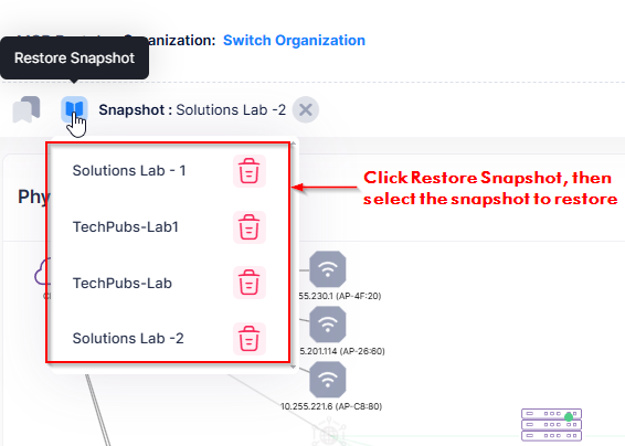
To restore a Topology Map screenshot, click on the Restore Snapshot icon, then select the snapshot file that you want to restore from the drop-down menu.
When you restore a snapshot of a Topology Map, the snapshot image does not change. For example, if you uploaded a background image for your Topology Map, then did a snapshot and a restore, the background image remains in place.
Importing/Exporting the Topology Map Layout
In addition to the snapshot/restore functionality, you can also import and export a Topology Map. This is particularly useful if you want to share your topology position layout with another user. For example, you can export your topology position layout to a text file (.txt) and send it to another user who can then import the position layout and save it to their own snapshot.
Importing a Topology Map
To import a Topology Map, click on the Import Device Layout icon in the top-right corner of the screen. You are prompted to locate and upload a Text File. The layout contained in the text file is displayed on the screen.
Exporting a Topology Map
You can export a Topology Map to a Text File or an SVG Document. To export the Map, click on the Export Data Options icon in the top-right corner of the screen and select “txt” or “svg” from the drop-down menu. You are then prompted to select the location where you want to download the exported file. Select the location on your computer, then click Save.
Working with Network Devices
You can view detailed information about a device or perform certain actions on a device by clicking on the device in the map. Actions can be performed on a single device or multiple devices. After selecting a device(s), you can perform one of the actions displayed in the Actions drop-down list. Note that the actions available depend on the device type(s) selected and whether or not you select a single device or multiple devices.
Viewing Device Information
Use the following methods for displaying device information on the Topology Map:
-
Hover the mouse over a device in the Map to display basic information.
-
Click on a device in the Map to display detailed device information in the Device Detail panel on the right side of the screen.
-
Click on a device in the Map, then on the Show/Hide Client icon to display clients that are connected to the device.
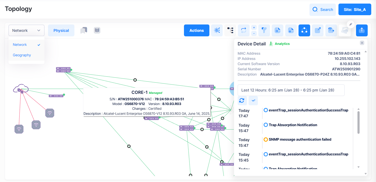
Displaying Basic Device Information
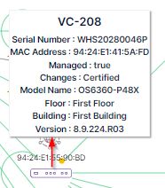
When you hover the mouse over a device in the Topology Map, the following window displays above the device showing basic information for the device:
-
Serial Number - The serial number of the device.
-
MAC Address - The MAC address of the device.
-
Managed - Is the device managed by OmniVista Cirrus (True or False).
-
Changes (Switch Only) - Are changes saved (Certified or Unsaved).
-
Model Name - The model name for the device.
-
Floor - The floor where the device is located within the Site building.
-
Building - The building where the device is located within the Site.
-
Version - The version of software running on the device.
Displaying Detailed Device Information
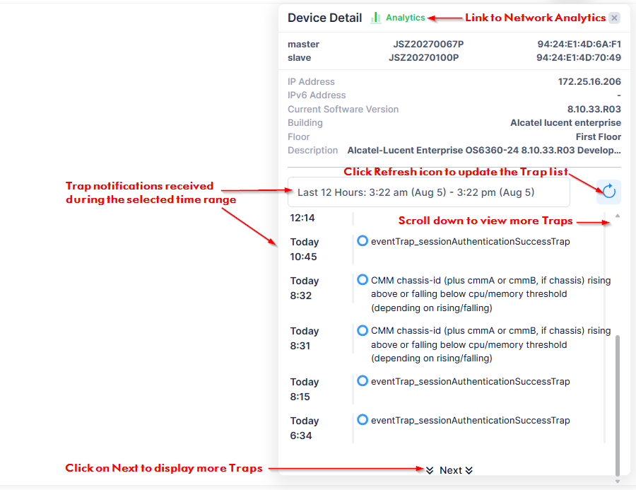
When you click on a device icon in the Topology Map, the following Device Detail window displays on the right-hand side of the screen showing additional device information:
-
Analytics - Click on this link to open the Network Analytics screen for the selected device.
-
MAC Address - The MAC address of a standalone device. This field is not displayed for switch Virtual Chassis (VC) configurations. Instead, the serial number and MAC address of each switch in the VC are displayed.
-
IP Address - The IP address of the device.
-
Current Software Version - The version of software currently running on the device.
-
Serial Number - The serial number of a standalone device. This field is not displayed for switch VC configurations. Instead, the Serial Number and MAC address of each switch in the VC are displayed.
-
Building - The Building where the device is located within the Site.
-
Floor - The Floor where the device is located within the Site.
-
Description - A description of the device received when the device was added to the Device Catalog.
-
Trap Notification List - A list of traps received from the device during the specified time range. Scroll down the list and click on Next to view more traps. Click the refresh icon to update the display from the OmniVista Cirrus database.
Displaying Clients Connected to a Device
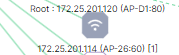
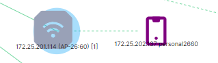
By default, device clients do not show on the Topology Map. If clients are connected to a device, the number of connected clients is displayed at the end of the Friendly Name in brackets. For example, AP 172.25.201.114 [1) has one connected client.
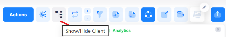
To display the connected clients, select the device and click on the Show/Hide Client icon located in the top-right corner of the screen.
The connected client(s) appear on the Map.
Note the following about displaying connected clients:
-
A wired client displays with a solid line between the client and the device.
-
A wireless client displays with a dashed line between the client and the device.
-
A phone icon is displayed for clients. However, if the client device type is a computer (including tablets) a computer icon is displayed.
You can also find a client by entering the client MAC address in the search box at the top-right corner of the screen. If the client is found, the device to which the client is connected is highlighted and the client device is displayed.
To view additional information about the client, click on the connected client icon. The Client Session History screen for the client will open in a new tab.
Performing Device Actions
You can perform device operations by selecting a device(s) in the Topology Map, then clicking on Actions to select one of the operations from the drop-down menu. Note that the Actions button does not appear until you select a device.
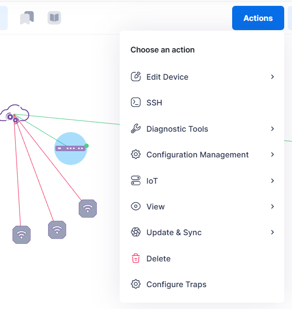
Refer to the Performing Device Operations online help for the Device Catalog for information about the options on the Action drop-down menu.
However, the Set as root action is specific to the Topology application.
-
Not all operations are supported on all devices, and some operations can only be performed on a single device, not multiple devices. If an action is not supported for the selected device(s), it is not included in the “Actions” drop-down list.
-
When you Ping a device from the Topology Map (Actions > Diagnostics Tools > Ping), the connectivity dot for the device changes to green (ON). The dot stays green for approximately two minutes. If after two minutes a message is received from the device, the dot stays green. However, if no message is received, the dot color changes to orange (warning) and the device is then greyed out after three minutes if no message is received.
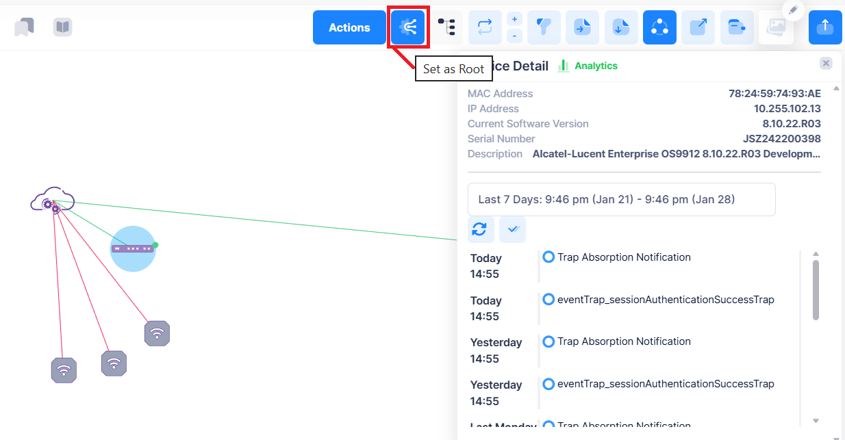
Setting the Root of the Topology Map
The root of the Topology Map is usually the upstream device; the device that provides Internet access. To change the root, click on the device you want to set as the root, then click on the Set as Root option. The Topology Map will automatically re-arrange devices around the new Topology root device.
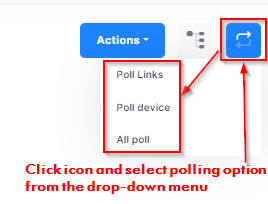
Polling Devices
You can poll devices to update device/link information. Click on the device that you want to poll, then click on the Poll icon and select the polling option from the drop-down menu.
Polling is supported only for switch devices in the topology; AP polling is not supported. When switches are polled, links between switches (Switch-Switch) and links between switches and APs (Switch-AP) are detected.
-
Poll Links - Causes an immediate poll of any links on the device(s).
-
Poll Device - Causes an immediate poll of the selected device(s).
-
All Poll - Causes an immediate poll of the device(s) and any links on the device(s).
Geography
The Geography view displays the site on a map based on its configured address. It offers a high-level overview of device distribution and site health, displayed within the Wi-Fi Heatmap.
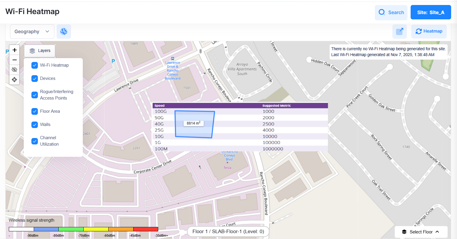
The Geography view supports multiple display layers, including:
-
Wi-Fi Heatmap
-
Devices
-
Rogue/Interfering Access Points
-
Floor Area
-
Walls
-
Channel Utilization
Clicking on All Sites displays the device discovery representation across all the configured sites in the map.
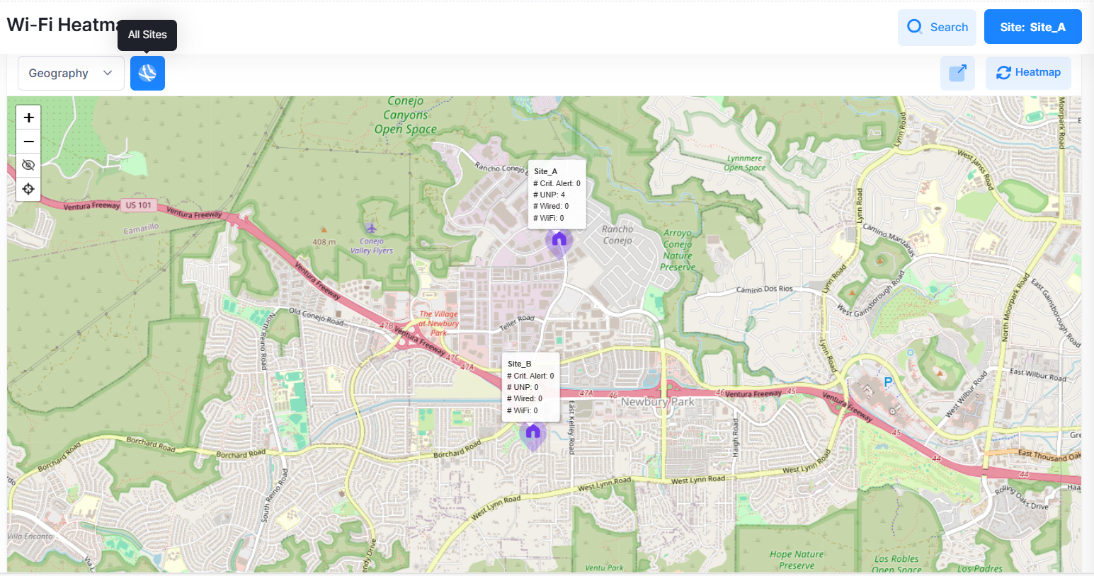
Click on the site to view the Wi-Fi Heatmap for the site.
You can also select the site using the Site: button on the top right of the screen.
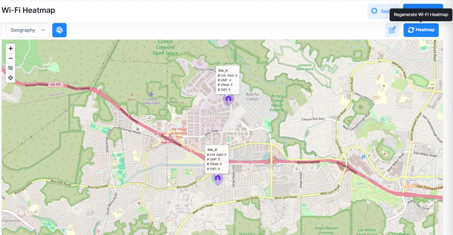
Click on the Heatmap icon on the top right of the screen to send a regeneration request for the Wi-Fi heatmap.
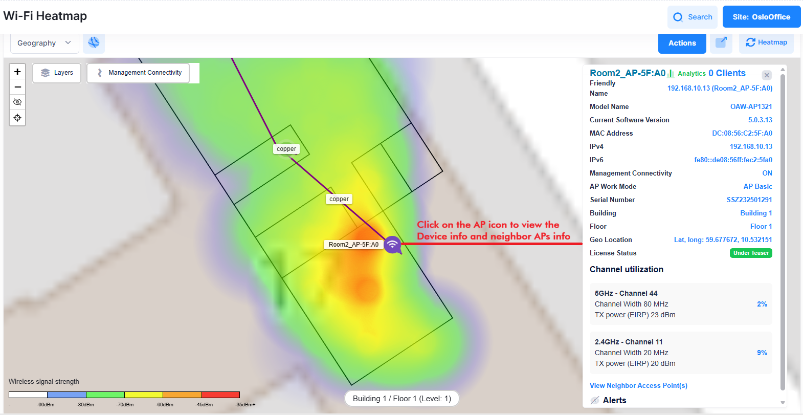
Wi-Fi Heatmap
Wi-Fi heatmap is a visual representation of the wireless signal coverage and strength of Access Points connected to the network. Creating a Wi-Fi heat map allows network administrators to visualize the real signal strengths of their wireless infrastructure, and more quickly understand which AP clients have limited or missing Wi-Fi connections.
The wireless devices are displayed as Wi-Fi logos. Click on any of the wireless device logos to view the detailed summary of that device as shown below.
The heatmap calculation is based on the position of the access points, operating on the 2.4 GHz frequency band with a transmit power of 6 dBm.
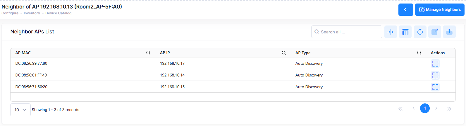
To view the list of neighboring Access Points detected for the specific device, click on Actions > View > Neighbor APs.
Show Mesh Topology
The graph depicting the mesh topology is presented within a modal window that can be accessed through the Wi-Fi heatmap. The wireless devices are displayed as Wi-Fi logos.
Select a device from the Heatmap. If the device is part of any Mesh network, the “Show Mesh Topology” link is displayed under the “Actions” section.
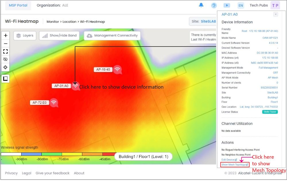
Click on Show Mesh Topology to launch the modal that displays topology in graphical format as shown below.
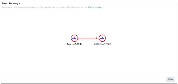
The format for the node label is 'Level: Name'.
The topology graph displays all devices that are part of the Mesh network, regardless of whether they are on the selected floor of the Heatmap or not. This means that the graph may show devices that are not included in the Heatmap from which it is launched.
Note: The Mesh links between the APs are displayed only when they exists.