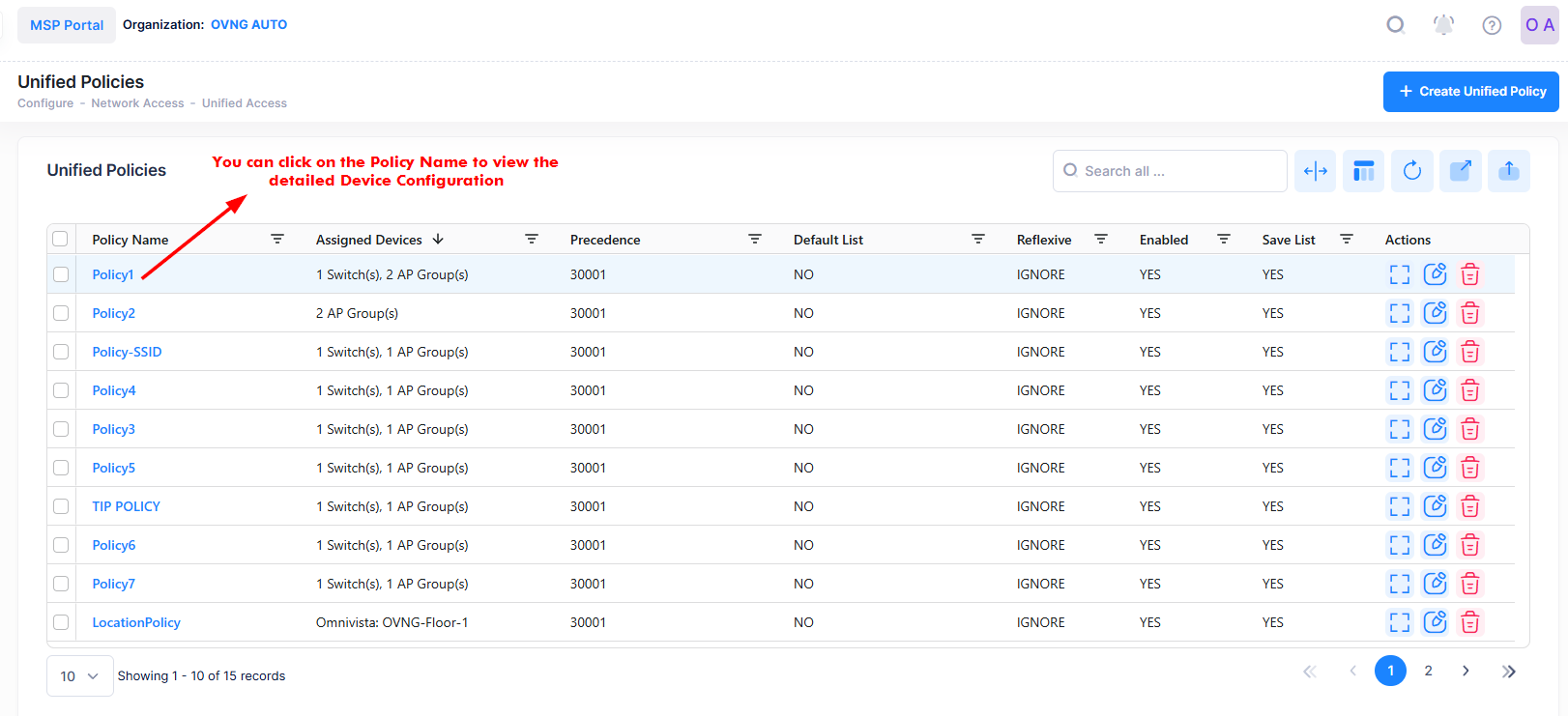
Unified Policies are QoS Policies that can be applied to devices. Use the Unified Policies screen to display information about all of the configured Unified Policies. This screen also allows you to create, edit, and delete Unified Policies on the network. To access the Unified Policies screen, click on Network Access > Unified Access > Unified Policies under the “Configure” section of the OmniVista Cirrus Menu.
Creating a Unified Policy
The Create Unified Policy screen is used to configure the Unified Policy Settings and Network Assignment settings for a unified policy. To access the Create Unified Policy screen, click on Create Unified Policy at the top of the Unified Policies screen, as shown above.
Consider the following use cases when configuring Unified Policies:
-
OmniVista Cirrus 10 does not use LDAP, so any Unified Policies created on a Switch via LDAP are not discovered; only policies configured through the Switch CLI are discovered. As a result, the Unified Policies screen displays only policies configured through the Switch CLI.
-
Child policy profiles (action, condition, validity period) can be shared among policy rules.
Example:
-
policy rule r1 condition r1 action r1 validity-period r1
-
policy rule r2 condition r1 action r1 validity-period r1
In this complex case, when you try to delete policy rule r2, only rule r2 will be deleted on both OmniVista Cirrus devices and the applied Switch devices. The child profiles (condition r1, action r1, validity period r1) will be retained because they are used by policy rule r1. They will only be deleted when no policies are using them. If you edit the child profile of policy rule r1, policy rule r2 will be affected because they are sharing the child profile.
-
If there are two policies with the same name but different child profiles between two Switch devices, there will be a mismatch between the profile template and device configuration.
Example:
-
Switch A has policy rule r1 condition r1 action r1 validity-period r1
-
Switch B has policy rule r1 condition r2 action r2 validity-period r2
Assuming that Switch A will report the polling data before Switch B, you should save the profile template of policy rule r1 with the child profile condition r1, action r1, and validity period r1. Subsequently, when Switch B reports the polling data for policy rule r1 but with a different child profile, you should only update the assignment for policy rule r1 instead of updating the profile with the new child profile. As a result, there will be a mismatch between policy rule r1 and Switch B. (Note: If rule r1 is edited without changing the device selection, the configuration on both Switch A and Switch B will be updated).
-
There are two platform types for the Switch devices: QoS1 and QoS2.
-
The QoS1 platform includes the following models: OS6860, OS6865, and OS6900-TOR, which require at least one configuration when creating a policy condition.
-
The QoS2 platform includes the following models: OS9900, OS6860N, OS6900-Yukon, OS6560, OS6465, OS6360, and OS6570, which allow the creation of a policy condition without any configuration.
-
As a result, you cannot apply a policy condition without criteria on the QoS1 platform.
-
The modification of Policy Rule which contains only a single L3 condition to another L3 condition is not allowed. If you want to add a condition with the existing condition, then first delete and re-create the policy with the new L3 condition.
-
The Switch device does not allow combining the L3 Condition Multicast IP with L2 Condition Source MAC, L3 Condition Source IP, L3 Condition DSCP/TOS, L4 Condition Service, L4 Condition Service Group, or Policy Action CIR.
The Create Unified Policy screen provides the following step-by-step process for creating an Unified Policy:
1. Unified Policy Settings
Basic Information
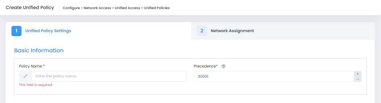
-
Policy Name - The name of the policy. The field must have at most 22 characters. The use of two special characters(/ or \) is not allowed for the Policy name.
-
Precedence - The Precedence value of the Policy (0 - 65535).
Advanced Options
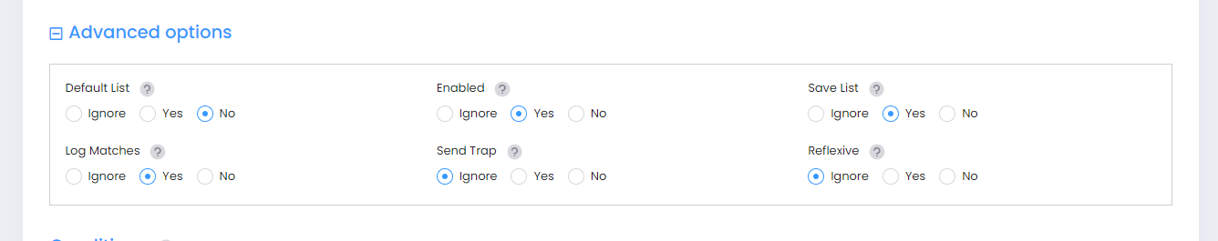
Click on Advanced options to display and configure the following options:
-
Default List - Adds the rule to the default policy list.
-
Enabled - Enables the policy.
-
Save List - Marks the policy rule so that it may be captured as part of the switch configuration.
-
Log Matches - Configures the switch to log messages about specific flows coming into the switch that match this policy rule.
-
Send Trap - Enables or disables traps for the rule. By default, it is set to Ignore. Since the Switch devices no longer support this option, therefore enabling it will have no effect on the Switch devices.
-
Reflexive - Enables support for Reflexive for the policy. Reflexive policies allow specific return connections that would normally be denied. Since the Switch devices no longer support this option, therefore enabling it will have no effect on the Switch devices.
Conditions
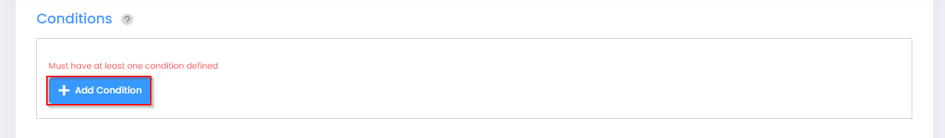
A Unified Policy is applied to client traffic that matches the condition(s) configured for the policy. At least one condition is mandatory. When multiple conditions are specified, all conditions must match for the policy to be applied to the client traffic.
When you create a Condition, the Condition(s) you configure must be true before traffic is allowed to flow. Click on Add Condition and select the Condition you want to configure from the “Choose a condition” drop-down menu. The configuration options for the selected Condition will display.
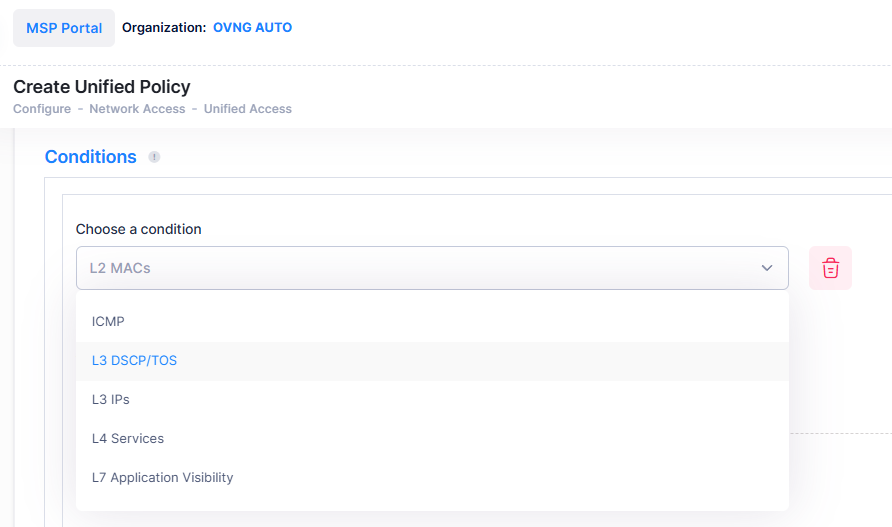
A brief description of each Condition is provided below. Click the hyperlink for each Condition for detailed configuration instructions.
-
L2 MACs - Create a Condition that applies the policy to traffic originating from a MAC address/group or to traffic flowing to a MAC address/group. (Note that, MAC Addresses cannot contain wildcard characters for both Access Points and Switches).
-
L3 IPs - Create a Condition that applies the policy to traffic originating from an IP address/network group or to traffic flowing to an IP address/network group. (Note that any IP address can be masked).
-
L3 DSCP/TOS - Create a Condition that applies the policy to traffic with a specified value in either the DSCP (Differentiated Services Code Point) byte or in the IP TOS (IP Type of Service) byte. Both DSCP and IP TOS are mechanisms used to convey QoS information in the IP header of frames.
-
L4 Services - Create a Condition that applies the policy to traffic flowing between two TCP or UDP ports, or to all traffic originating from a TCP or UDP port, or to all traffic flowing to a TCP or UDP port. You can also create a Condition using an existing service/service group.
-
ICMP - Create a Condition that applies the policy to traffic with a specified ICMP Type or Code value.
-
L7 Application Visibility - Create a Condition that applies the policy to traffic flowing to and from an Application Group or Application.
L2 MACs
A MAC Condition applies the Policy to traffic flowing from/to a MAC Address/Group. Note that Layer 2 Conditions (conditions that specify MAC Addresses) are "lost" when traffic passes through a router. For this reason, it may be advisable to specify other types of Conditions (such as a Layer 3 Condition, which specifies IP Addresses) when traffic is expected to travel more than one router hop.
When you select the L2 MACs condition, the following parameters to configure a single/group source MAC address or a single/group destination MAC address will display.
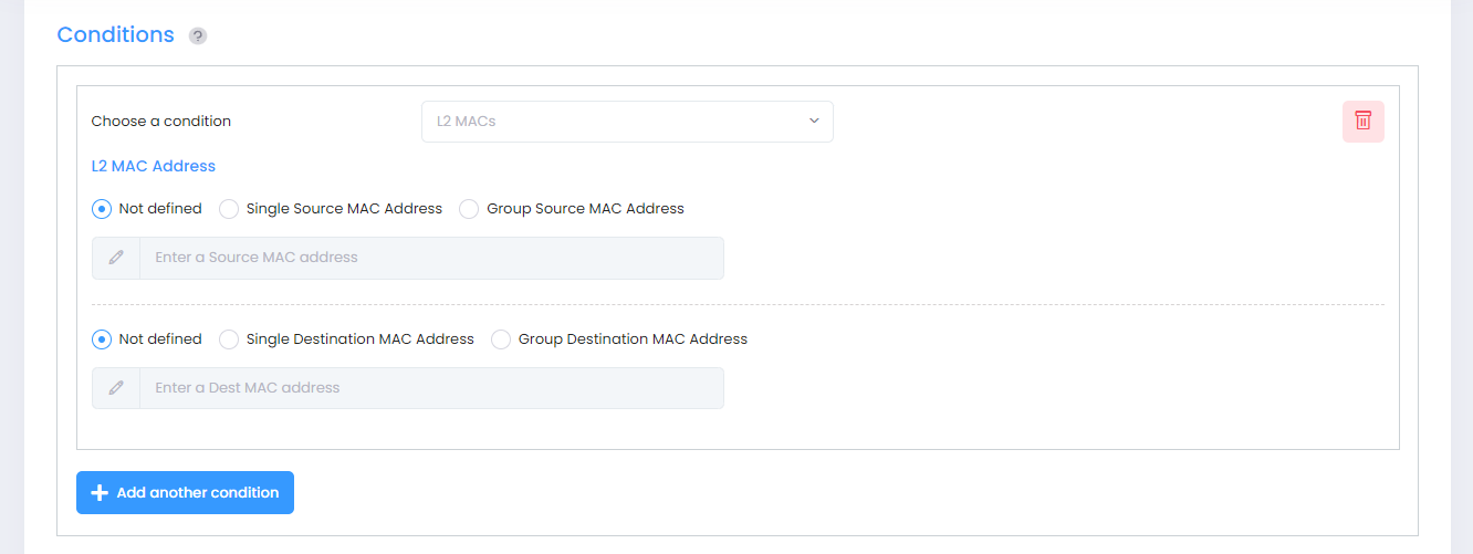
Select the parameter(s) you want to configure by selecting the applicable radio button. For Source/Destination MAC Address, click on Single Source/Destination MAC Address to configure a single MAC Address or click on Group Source/Destination MAC Address to configure a MAC Address Group. If you select the Group option, you will then be prompted to select an existing MAC Address Group or create a new group.
-
Not defined - This option specifies that there is no criteria for the policy.
-
Single Source MAC Address/Group - Configuring a Source MAC Address/Group Condition restricts the policy to traffic that flows from this MAC Address/Group only. If you do not select this option, you are effectively stating that the Source MAC Address/Group traffic is not a criterion for the policy.
-
Single Destination MAC Address/Group - Configuring a Destination MAC Address/Group Condition restricts the policy to traffic that flows to this MAC Address only. If you do not select this option, you are effectively stating that the Destination MAC Address/Group traffic is not a criterion for the policy.
Notes:
-
Conditions that specify both a source and a destination MAC address may be rejected by some devices as invalid. However, if you wish to create policies for both source and destination traffic, you can create one policy for the source traffic and a second policy for the destination traffic.
-
The following MAC address ranges are assigned to Alcatel-Lucent Enterprise voice devices and Alcatel-Lucent Enterprise IP phones.
-
Voice Devices
-
00809F3A0000 - 00809F3AFFFF
-
00809F3B0000 - 00809F3BFFFF
-
00809F3C0000 - 00809F3CFFFF
-
-
IP Phones
-
00809F3D0000 - 00809F3DFFFF
-
-
Multi-Media Devices
-
00809F3E0000 - 00809F3EFFFF
-
00809F3F0000 - 00809F3FFFFF
-
-
L3 IPs
An IP Condition applies the Policy to traffic originating from, or flowing to, an IP Address/IP Network group. Any IP Address can be masked. Note that a Condition that specifies both a Source and Destination IP Address/Network Group will be rejected by the device as invalid. However, if you wish to create policies for both Source and Destination traffic, you can create one policy for the Source traffic and a second policy for the Destination traffic.
When you select the L3 IPs condition, the following parameters to configure a single/group source IP address or a single/group destination IP address will display.
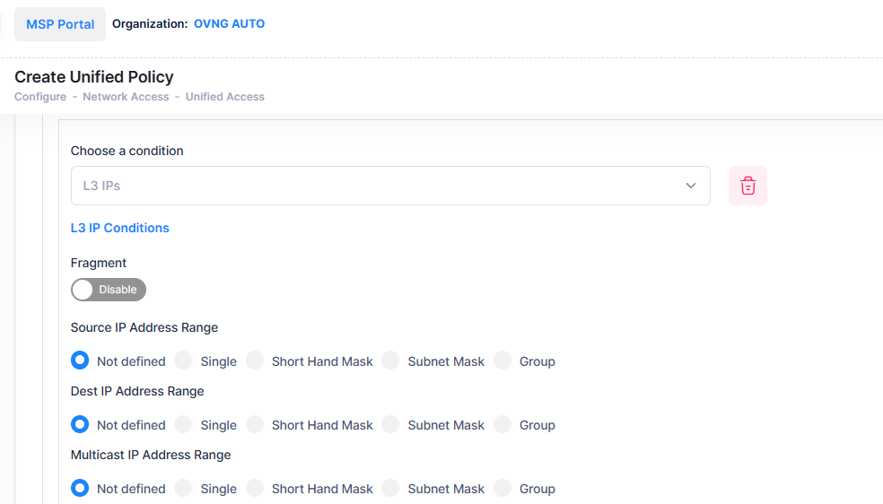
Select the parameter(s) you want to configure by selecting the applicable radio button. For Source/Destination/Multicast IP Address, click on Single to configure a single IP Address (and Shorthand or Subnet Mask, if applicable), or click on Group to configure an IP Group. If you select the Group option, you will then be prompted to select an existing IP Group or create a new group.
-
Fragment - Select this checkbox to restrict the policy to TCP packet fragments. (Note: This option is available only for Switch devices configuration).
-
Not defined - This option specifies that there is no criteria for the policy.
-
Single Source IP Address - Configuring a Source IP Address/Group Condition restricts the policy to traffic that flows from this IP Address only. If you do not select this option, you are effectively stating that the Source IP Address/Group traffic is not a criterion for the policy.
-
Single Destination IP Address - Configuring a Destination IP Address/Group Condition restricts the policy to traffic that flows to this IP Address only. If you do not select this option, you are effectively stating that the Destination IP Address/Group traffic is not a criterion for the policy.
-
Single Multicast IP Address - Configuring a Multicast IP Address/Group Condition restricts the policy to traffic that flows to this IP Multicast Address Group only. If you do not select this option, you are effectively stating that the Destination IP Multicast Address/Group or Subnet Mask/Group traffic is not a criterion for the policy.
When configuring an IP Address Condition, you can also click either the Shorthand Mask or Subnet Mask button to configure a Subnet Mask. If you are using a Shorthand Mask, select a value from the Shorthand Mask drop-down list. If you are using a full Subnet Mask, select a value from the Subnet Mask drop-down list. Note that the * wildcard character is not allowed in IP addresses.
Important Note:
-
When creating an IP Condition for a NAT Action, you must specify an IP Network Group in the Condition. NAT will only work when both the Condition and Action specify network groups. To create a "One-to-Many" Condition and action, create a Network Group with a single entry for the Condition.
-
If you configure L3 IP Conditions with Source IP Address Range and Destination IP Address Range with Short Hand Mask set to 0, the Switch will reflect the Source or Destination IP address as “ANY”.
L3 DSCP/TOS
A DSCP/TOS Condition applies the Policy to incoming traffic that has a specified value in either the DSCP (Differentiated Services Code Point) byte or in the TOS (Type of Service) byte. Both DSCP and TOS are mechanisms used to convey QoS information in the IP header of frames. DSCP and TOS are mutually exclusive - you can use either DSCP or TOS but not both.
When you select the L3 DSCP/TOS condition, the following parameters to configure a single/group source IP address or a single/group destination IP address will display.
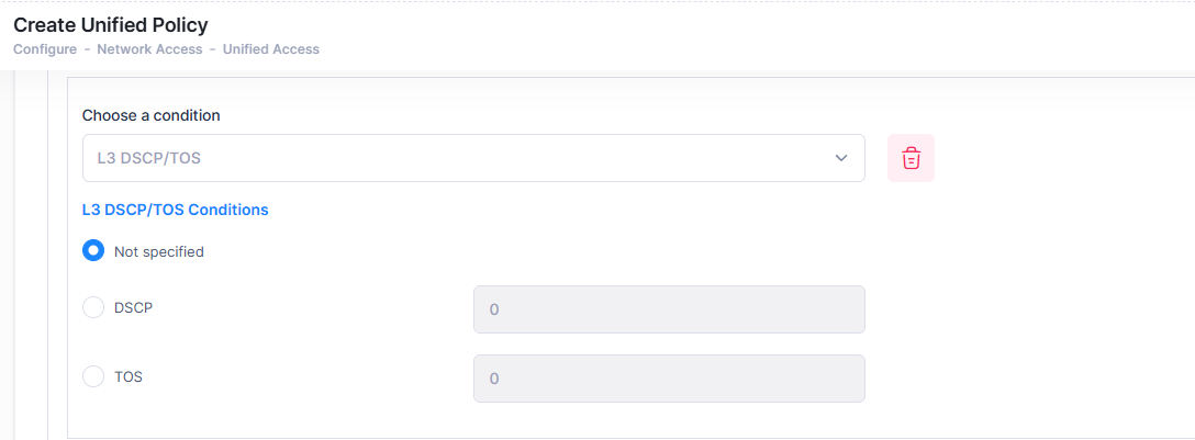
Click on the applicable radio button (DSCP or TOS) and enter a value.
-
Not specified - There is no criteria for the policy.
-
Differentiated Service Code Point - Defines the QoS treatment a frame is to receive from each network device. This is referred to as per-hop behavior. If you are using DSCP, you can define any value in the range 0 - 63 as the DSCP value in the IP header of the frame. Traffic that contains this value will match this condition.
-
Type of Service Precedence- A TOS value creates a condition that applies the policy to traffic that has the specified TOS value in the IP header of frames. Enter any value from 0 - 7 to specify the value of the precedence field in the TOS byte that will match this condition. A value of 7 has the highest precedence and a value of 0 has the lowest.
L4 Services
A Service Condition applies the policy to Service Protocol traffic (TCP or UDP) flowing from/to two TCP or UDP ports, or to traffic flowing from/to a TCP or UDP Service or Service Group. When you select the L4 Services condition, the following parameters to configure the type of Service Condition will display:
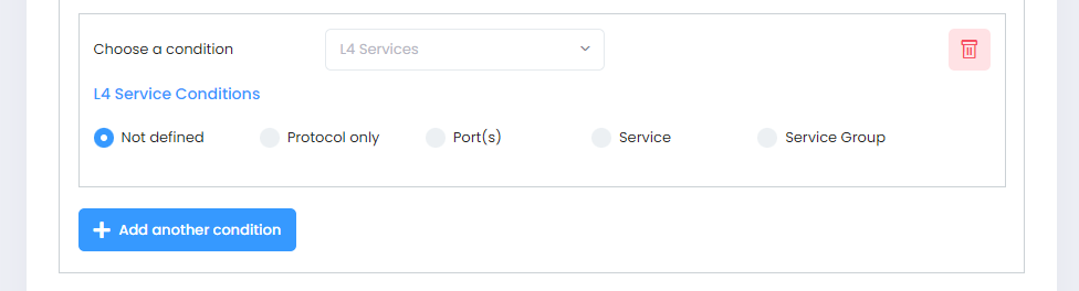
Select a type of Service Condition you want to configure, then configure the parameter(s) as described below.
-
Not defined - This option specifies that there is no criteria for the policy.
-
Protocol Only - Select TCP,UDP or ICMP to create a condition for a Service Protocol only.
-
Port(s) - To configure the Condition for a specific Service Port, select a Source and Destination Port from the drop-down menu to specify a specific port for the service you selected. You can also click on Add New to create new Service Ports.
-
Service - Select a Service from the drop-down menu. You can also click on Add New to create a new Service.
-
Service Group - Select a Service Group from the drop-down menu. You can also click on Add New to go create a new Service Group.
ICMP
An ICMP Condition applies the policy to traffic with the specified ICMP Type/Code value. Traffic that contains this value will match this condition. When you select the ICMP condition, the following parameters to configure the type of Condition will display:
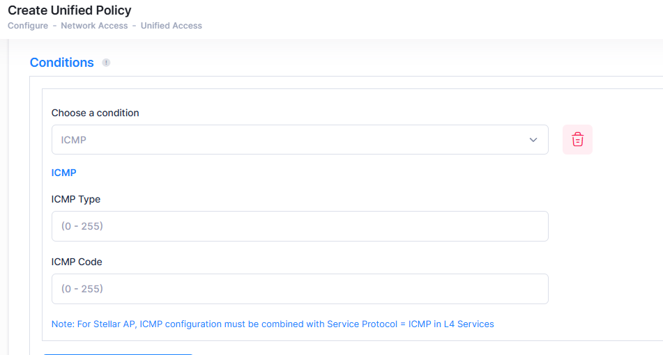
You can configure the parameter(s) as described below.
-
ICMP Type - Enter any value between 0 - 255 for the ICMP Type.
-
ICMP Code - Enter any value between 0 - 255 for the ICMP Code.
Note: For Steller Access Points, ICMP configuration must be combined with Service protocol = ICMP in L4 Services.
L7 Application Visibility
An Application Visibility Condition applies the policy to traffic flowing to and from an Application Group or Application. When you select the L7 condition, the following parameters to configure the type of Condition will display:
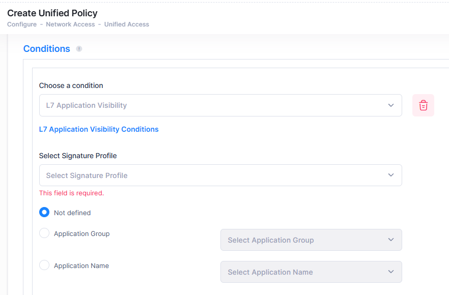
Select a type of L7 Condition you want to configure, then configure the parameter(s) as described below.
-
Select Signature Profile - Select a signature profile from the drop-down menu.
-
Not defined - This option specifies that there is no criteria for the policy.
-
Application Group - Select an Application Group from the drop-down menu.
-
Application Name - Select an Application from the drop-down menu.
Note: The drop-down menus are populated with the Application Groups/Applications contained in the Signature Profile for the selected Stellar APs. If you select multiple APs, only those Application Groups/Applications common to all APs will be displayed.
Note: To create a Quality of Service (QoS) policy for multiple applications, you can create a custom group within the Signature profile. By using the “Custom Application Group" feature, you can define a single policy that includes all applications in that group. This method is advantageous because any modifications to the applications within the custom group will not necessitate editing the policies or pushing updated policies to managed devices.
Actions
A Unified Policy Action enables you to specify the treatment traffic receives when it flows. This includes the priority the traffic will receive, its minimum and maximum output rates, and the values to which specified bits in the frame headers will be set upon egress from the device. When the conditions specified by the Unified Policy Condition are true, traffic will flow as specified by the Unified Policy Action.
A brief description of each Action is provided below. Click the hyperlink for each Action for detailed configuration instructions.
-
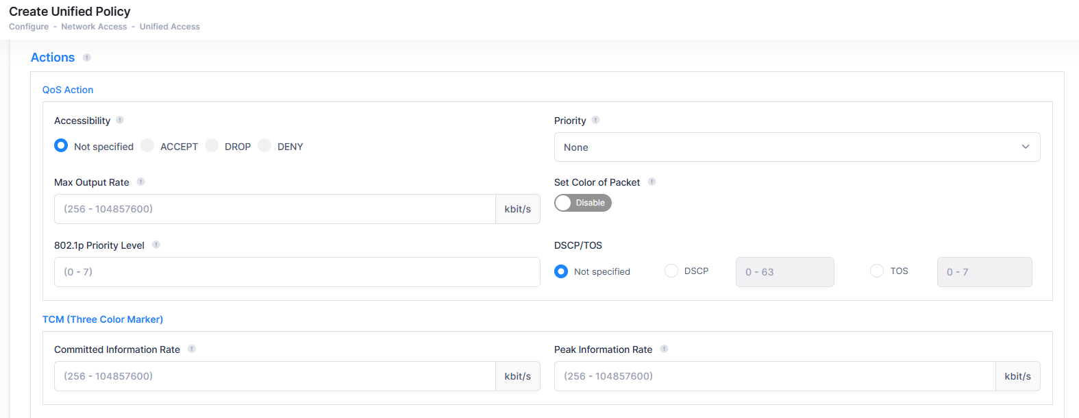
QoS - Create an Action to specify QoS actions to impose on traffic that meets the configured policy condition(s). When the conditions specified by the policy are true, traffic will flow as specified by the policy action.
-
TCM - Create an Action to specify Tri-Color Marking (TCM) actions to impose on traffic that meets the configured policy condition(s). TCM provides a mechanism for policing network traffic by limiting the rate at which traffic is sent or received on a device interface. TCM meters traffic based on user-configured packet rates and burst sizes and "marks" the metered packets as green, yellow, or red based on whether the traffic meets the configured rates. This "color marking" determines the packet's precedence when congestion occurs.
-
QoS - The QoS Policy Action option enables you to specify QoS actions to impose on traffic that meets the configured policy condition(s). When the conditions specified by the policy are true, traffic will flow as specified by the policy action.
-
Accessibility - Set the Action to Accept, Drop or Deny traffic that meets the configured condition(s). The Deny option will only be available for Switch devices.
-
Accept- Specifies that the switch should accept the flow.
-
Drop- Specifies that the switch should silently drop the flow.
-
Deny- Specifies that the switch should drop the flow and issue an ICMP message indicating the flow was dropped for administrative reasons. Currently this option will provide the same result as drop; that is, the flow is silently dropped.
-
-
Priority - Specify QoS priority the traffic will receive if it meets the configured condition(s).
-
Platinum priority provides the highest quality of service (and maps to a firmware priority of 7).
-
Gold provides the next-highest quality of service (and maps to a firmware priority of 5).
-
Silver provides the next-highest quality of service (and maps to a firmware priority of 3).
-
Bronze provides the same quality of service as best effort (and maps to a firmware priority of 1). A separate egress queue is maintained in the hardware for traffic of each different priority.
-
-
Max Output Rate - Specify the maximum amount of traffic, in kilobits-per-second, which is guaranteed to be transmitted. Even if no other traffic exists, the output will be limited to the rate specified here.
-
802.1p Priority Level - If you want outgoing packets tagged with an 802.1b priority level, set the 802.1p Priority Level field value between 0 to 7 to specify the desired outgoing 802.1p priority for the traffic. A value of 7 indicates the highest priority and a value of 0 indicates the lowest priority.
-
Set Color of Packet - Enables/Disables Three Color Marking (TCM) for output traffic flows. This parameter is not supported on Access Point devices and is ignored when applied to those devices.
-
DSCP/TOS - Enable/Disable DSCP/TOS Precedence.
-
-
TCM (Three Color Marker) - The TCM Policy Action option enables you to specify Three-Color Marking (TCM) actions action to impose on traffic that meets the configured policy condition(s). TCM provides a mechanism for policing network traffic by limiting the rate at which traffic is sent or received on a switch interface.
-
Committed Information Rate - The guaranteed bandwidth in bits-per-second, for all traffic that ingresses on the port.
-
Peak Information Rate - The peak bandwidth in bits-per-second, for all traffic that ingresses on the port.
-
Validity Period
The Validity Period enables you to add a validity period to a condition by specifying the time periods when the policy is active and enforced.
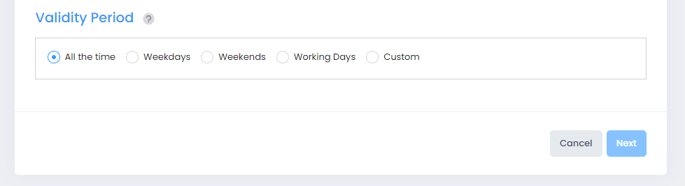
Select a validity period for the Unified Policy.
-
All The Time - The policy will be enforced all days of the week, all months of the year, and all hours of the day.
-
Weekdays - The policy will be enforced on weekdays (Monday - Friday), all months of the year. Each weekday is 24 hours (midnight to midnight).
-
Weekends - The policy will be enforced on Saturday and Sunday, all months of the year. Each Saturday and Sunday is 24 hours (midnight to midnight).
-
Working Days - The policy will be enforced on weekdays (Monday - Friday), from 9:00 a.m. to 5:00 p.m., all months of the year.
-
Custom - Select to create a custom validity period by specifying specific days, months, and times.
Click on Next button to configure Network Assignments for the Unified policy.
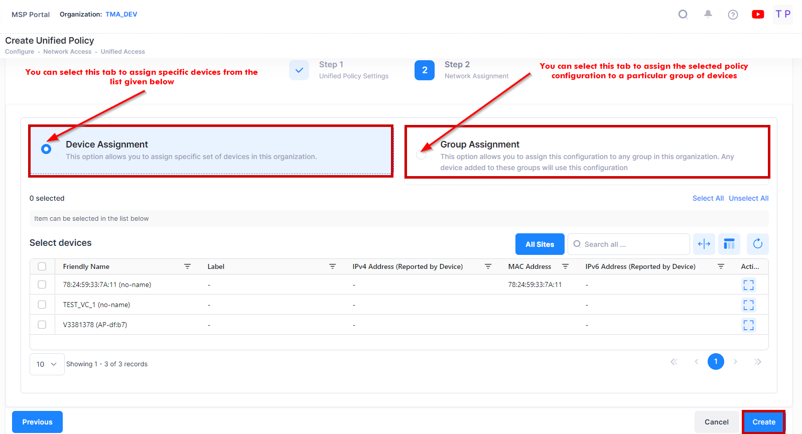
2. Network Assignments
The Network Assignments tab is used to select the AP Group(s) within a Site(s) and specific Switch devices to which the Unified Policy will be applied to devices within those groups. Complete the network assignments as described below, then click on Create to create the Unified Policy.
-
Device Assignment - Select the specific set of Devices from the available list to assign the policy.
-
Group Assignment - Select the specific group of Devices from the available list to assign the policy. The Unified Policy will be applied to the selected group of devices from the list.
Note: If a Unified Policy fails to apply to devices, re-apply the policy without changing the configuration. Edit the profile (or a linked profile that supports device assignment) to remove the devices, then re-add the devices in the device assignment tab.
Note: For the selection of an AP Group or Device, follow the below criteria:
-
You can define a Unified Policy without selecting an AP Group or Device
-
You can select only AP Groups to apply the Unified Policy
-
You can select only Switch devices to apply the Unified Policy
-
You can select both AP Groups and Switch devices to apply the Unified Policy
-
You can filter the Switch devices based on labels.
-
When you type characters in the device list field, the list of devices matching the typed characters will be displayed.
Editing a Unified Policy
Select the policy in the Unified Policy list and click on the Edit icon to bring up the Edit Unified Policy screen.
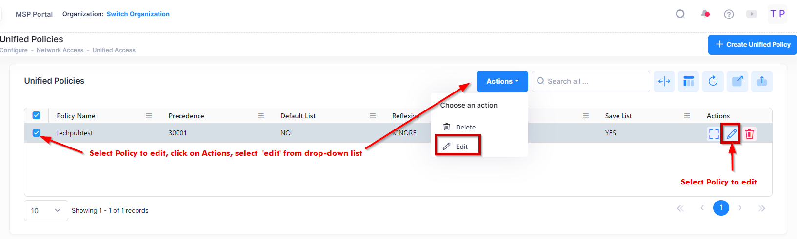
Use one of the following methods to access the Edit Access Role Profile screen (as shown above):
-
Select the profile to edit by clicking on the checkbox next to the profile, click on Actions, then select Edit from the drop-down menu.
-
Click on the pencil icon under the “Actions” column next to the profile that you want to edit.
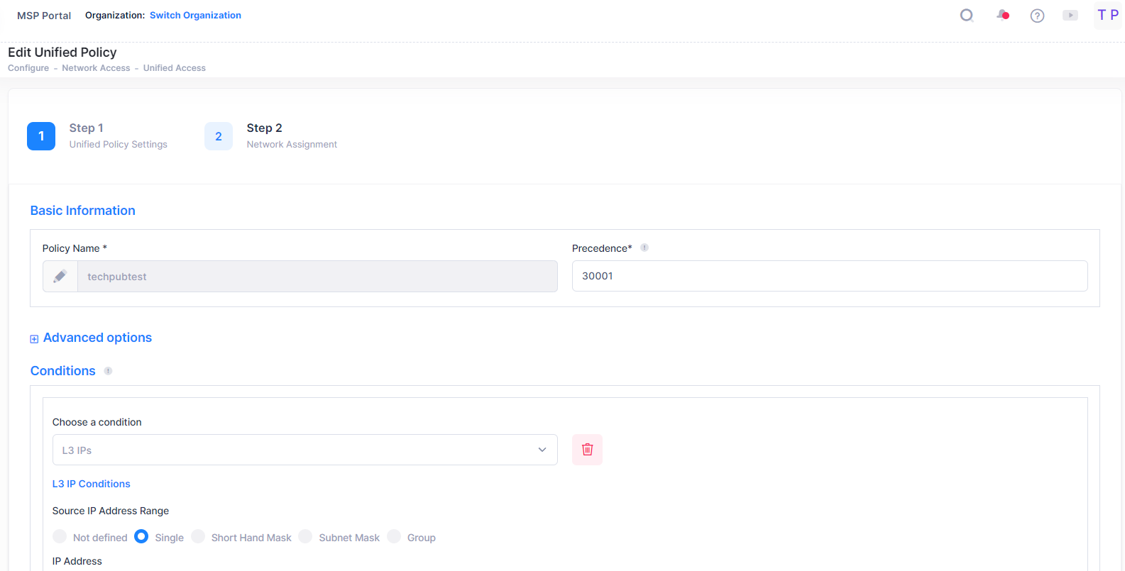
The following Edit Access Role Profile screen displays. Edit the fields as described above, then click on Save.
Note: If a Unified Policy fails to apply to devices, re-apply the policy without changing the configuration. Edit the profile (or a linked profile that supports device assignment) to remove the devices, then re-add the devices in the device assignment tab.
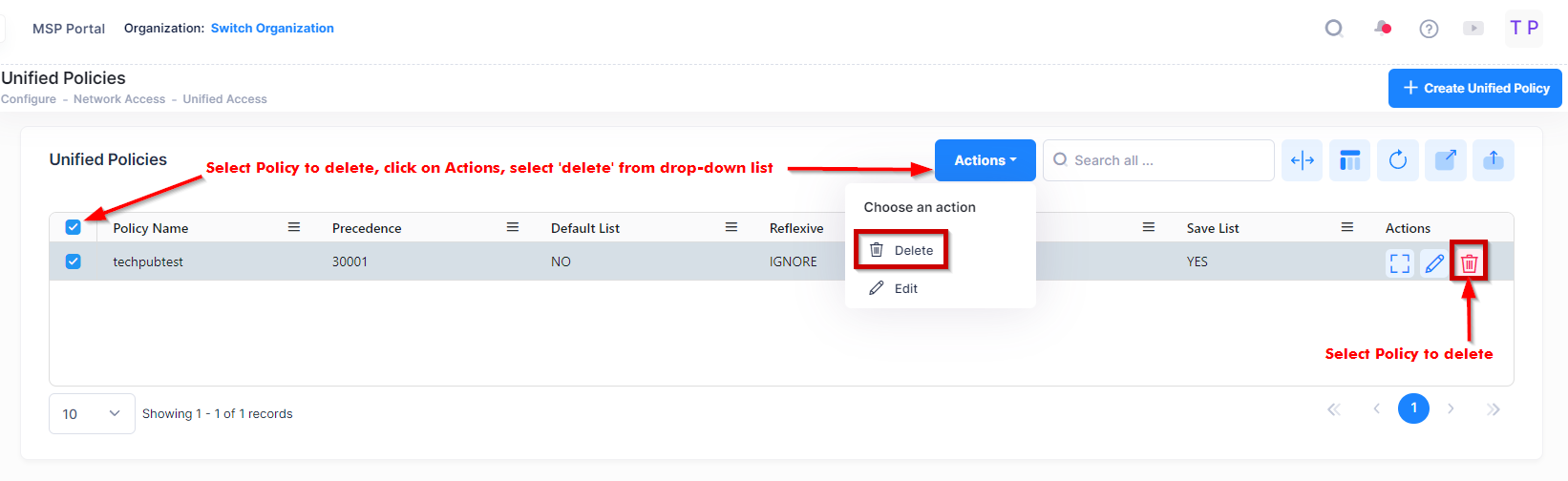
Deleting a Unified Policy
To delete an Unified Policy, use one of the following methods to select the policy you want to delete:
-
Select the profile to delete by clicking on the checkbox next to the profile, click on Actions, then select Delete from the drop-down menu.
-
Click on the trash can icon under the “Actions” column next to the profile that you want to delete.
When you select the profile you want to delete, the following confirmation prompt appears:
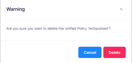
Click on Delete to confirm that you want to delete the Unified Policy.
Display Assigned Switch Configuration Details
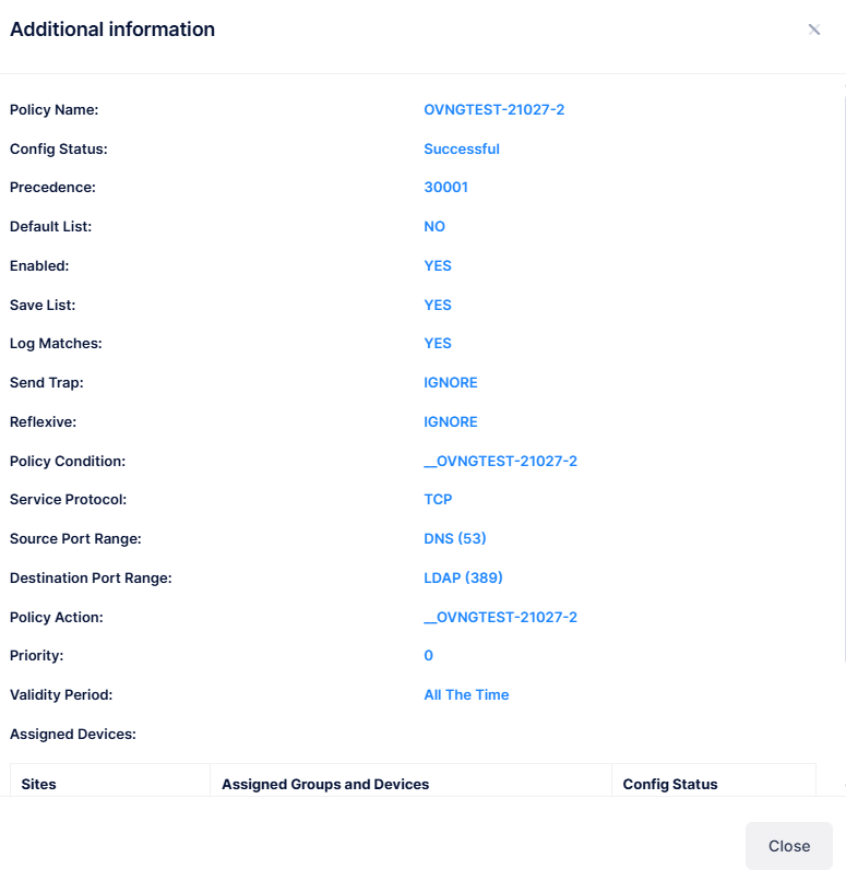
The Unified Policies displays information for the configured Unified Policies. You can click on the Policy Name to view the assigned Switch configuration details of a specific Policy as shown below.
The below screen appears:
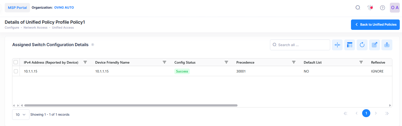
This screen also allows you to export, search and filter the data. You can click the back icon on the top right to navigate to the Unified Policy page.
The following Device Configuration of the selected Policy is displayed.
-
IPv4 Address - The IPv4 address of the device.
-
Device Friendly Name - The name assigned to the device is derived from the Preferred Device Naming convention specified in the user preference settings. By default, the Friendly Name is set to IP Address (System Name).
-
Config Status - The configuration status of the device (Successful, Failed, or Pending).
-
Pending - The configuration is being pushed to the device and is still not receiving a response from the device.
-
Failed - The configuration failed to apply to the device. Possible reasons include a timeout while applying the configuration due to the device being unreachable or a network issue, or the configuration being invalid and rejected by the device. Check alerts to identify the specific reason.
-
Successful - The configuration is pushed to the device successfully.
-
-
Precedence - The Precedence value of the Policy (0 - 65535).
-
Enabled - Indicates whether or not the Policy is enabled.
-
Log Matches - Indicates whether or not matches to this rule are logged in the QoS Log.
-
Reflexive - Indicates whether or not the Policy is reflexive. Reflexive Policy Rules allow specific return connections that would normally be denied (Yes/No).
-
Default List- Indicates whether or not the Policy is saved to the Default Policy List. By default, a Policy Rule is added to this list when it is created. A Policy Rule remains a member of the Default List even when it is subsequently assigned to additional Policy Lists.
-
Save List - Indicates whether or not the rule will be recorded during a snapshot command.
-
Send Trap - Indicates whether or not an SLA Policy Trap is configured for the policy.
Note: You can now view the current policy configuration for each switch assigned to a Unified Policy. You can edit the configuration on one or more assigned devices directly. If a device's configuration differs from the policy, the mismatched attributes will be highlighted, and you will have the option to synchronize them.
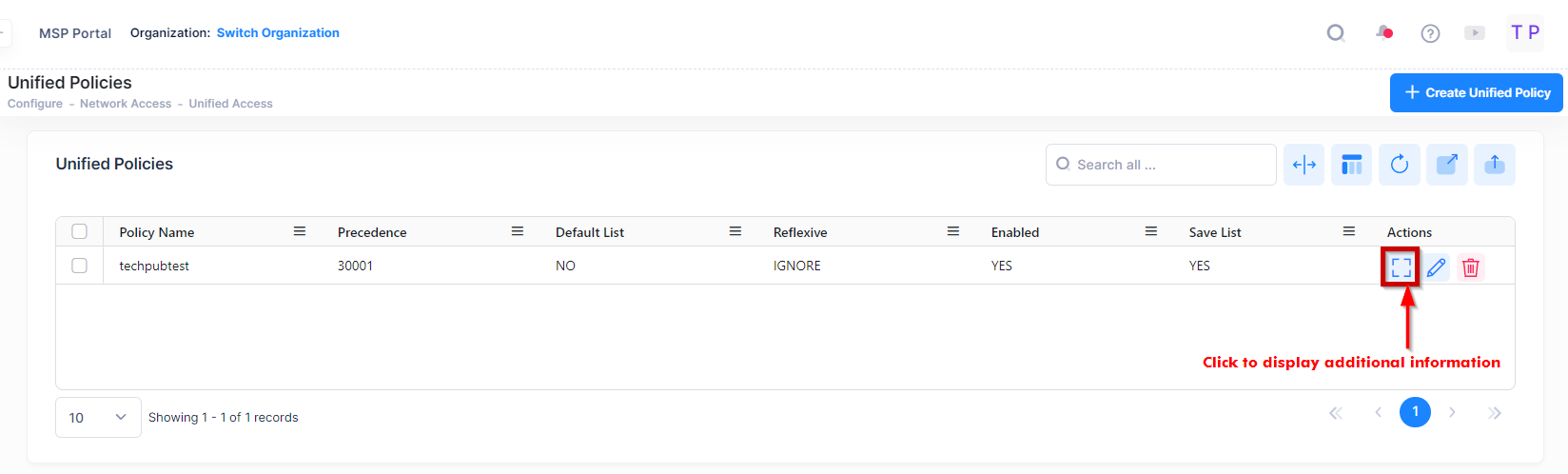
Display Unified Policy Additional Information
To display detailed information about a specific policy, you can click on the Additional Information icon under the “Actions” column.